
How to Use RF-LINK_TX: Examples, Pinouts, and Specs
 Design with RF-LINK_TX in Cirkit Designer
Introduction
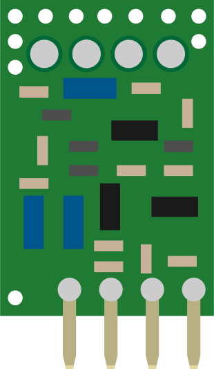
The RF-LINK_TX is a radio frequency (RF) transmitter module manufactured by SparkFun Electronics, with part IDs WRL-08945 and WRL-08946. This module is designed for wireless communication, enabling the transmission of data over short to medium distances. It operates in the unlicensed ISM (Industrial, Scientific, and Medical) frequency bands, making it suitable for a wide range of applications.
Explore Projects Built with RF-LINK_TX
 Open Project in Cirkit Designer
 Open Project in Cirkit Designer
 Open Project in Cirkit Designer
 Open Project in Cirkit Designer
Explore Projects Built with RF-LINK_TX
Open Project in Cirkit DesignerOpen Project in Cirkit DesignerOpen Project in Cirkit DesignerOpen Project in Cirkit DesignerCommon Applications and Use Cases
- Wireless remote controls (e.g., garage doors, home automation)
- Data transmission for IoT devices
- Wireless sensor networks
- Robotics and RC vehicles
- Alarm and security systems
Technical Specifications
The RF-LINK_TX module is compact and easy to integrate into various projects. Below are its key technical specifications:
| Parameter | Value |
|---|---|
| Operating Voltage | 3.3V to 12V |
| Operating Frequency | 315 MHz or 433 MHz (model-specific) |
| Transmission Power | Up to 10 mW |
| Data Rate | Up to 10 kbps |
| Range | Up to 500 ft (line of sight) |
| Modulation Type | Amplitude Shift Keying (ASK) |
| Dimensions | 19mm x 19mm x 7mm |
| Operating Temperature | -20°C to +70°C |
Pin Configuration and Descriptions
The RF-LINK_TX module has a simple pinout, as shown in the table below:
| Pin | Name | Description |
|---|---|---|
| 1 | VCC | Power supply input (3.3V to 12V) |
| 2 | DATA | Data input pin for transmitting digital signals |
| 3 | GND | Ground connection |
| 4 | ANT | Antenna connection for RF signal transmission |
Usage Instructions
The RF-LINK_TX module is straightforward to use and can be integrated into a variety of circuits. Below are the steps and considerations for using the module:
Connecting the Module
- Power Supply: Connect the VCC pin to a regulated power source (3.3V to 12V). Ensure the voltage matches the module's requirements to avoid damage.
- Ground: Connect the GND pin to the ground of your circuit.
- Data Input: Connect the DATA pin to the digital output of a microcontroller or other data source.
- Antenna: Attach a suitable antenna to the ANT pin to maximize transmission range. A simple wire of appropriate length (quarter wavelength of the operating frequency) can serve as an antenna.
Important Considerations
- Antenna Design: The length of the antenna should be approximately 23 cm for 315 MHz or 17 cm for 433 MHz to optimize performance.
- Interference: Operate the module in an environment with minimal RF interference for best results.
- Data Encoding: Use a suitable encoding scheme (e.g., Manchester encoding) to ensure reliable data transmission.
- Regulatory Compliance: Ensure compliance with local regulations for RF transmission in the ISM bands.
Example: Using RF-LINK_TX with Arduino UNO
Below is an example of how to use the RF-LINK_TX module with an Arduino UNO to transmit data:
/*
  Example: Transmitting data using RF-LINK_TX with Arduino UNO
  This code sends a simple "Hello, World!" message repeatedly.
*/

#define DATA_PIN 3  // Connect the DATA pin of RF-LINK_TX to Arduino pin 3

void setup() {
  pinMode(DATA_PIN, OUTPUT);  // Set the DATA pin as an output
}

void loop() {
  // Transmit a simple signal (e.g., toggling the DATA pin)
  digitalWrite(DATA_PIN, HIGH);  // Send HIGH signal
  delay(100);                    // Wait for 100 ms
  digitalWrite(DATA_PIN, LOW);   // Send LOW signal
  delay(100);                    // Wait for 100 ms
}
Best Practices
- Use a decoupling capacitor (e.g., 0.1 µF) across the VCC and GND pins to reduce noise.
- Keep the antenna away from other components to avoid signal degradation.
- Test the module in an open area to evaluate its maximum range.
Troubleshooting and FAQs
Common Issues and Solutions
No Signal Transmission
- Cause: Incorrect wiring or insufficient power supply.
- Solution: Double-check the connections and ensure the power supply voltage is within the specified range.
Short Transmission Range
- Cause: Poor antenna design or interference.
- Solution: Use a properly sized antenna and test in an environment with minimal RF interference.
Data Corruption
- Cause: High noise levels or lack of proper encoding.
- Solution: Implement data encoding (e.g., Manchester encoding) and use error-checking mechanisms.
Overheating
- Cause: Operating the module at a voltage higher than specified.
- Solution: Ensure the power supply voltage does not exceed 12V.
FAQs
Q1: Can I use the RF-LINK_TX module with a 5V microcontroller?
A1: Yes, the module is compatible with 5V logic levels. However, ensure the power supply voltage is within the 3.3V to 12V range.
Q2: What type of antenna should I use?
A2: A simple wire antenna of quarter-wavelength (23 cm for 315 MHz or 17 cm for 433 MHz) works well. For better performance, you can use a commercially available RF antenna.
Q3: Can I use multiple RF-LINK_TX modules in the same area?
A3: Yes, but ensure they operate on different frequencies or use unique data encoding to avoid interference.
Q4: What is the maximum data rate supported?
A4: The module supports data rates of up to 10 kbps.
By following this documentation, you can effectively integrate the RF-LINK_TX module into your projects and troubleshoot common issues.