How to Use Энкодер: Examples, Pinouts, and Specs
Introduction
An encoder is a device that converts information from one format or code to another. It is commonly used in control systems to provide feedback on position, speed, or direction. Encoders are essential in applications requiring precise motion control, such as robotics, CNC machines, and industrial automation. They are available in various types, including rotary and linear encoders, and can output digital or analog signals depending on the design.
The Arduino Энкодер is a versatile rotary encoder designed for use in microcontroller-based projects. It is ideal for applications such as user input devices (e.g., volume knobs or menu navigation), motor control systems, and position tracking.
Explore Projects Built with Энкодер
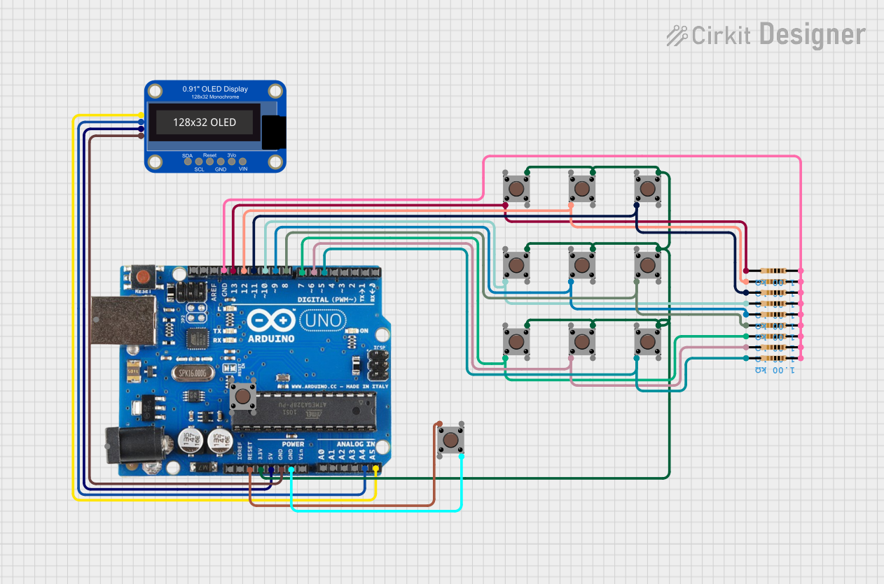

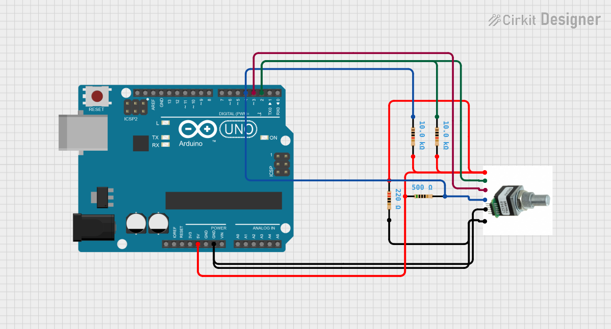
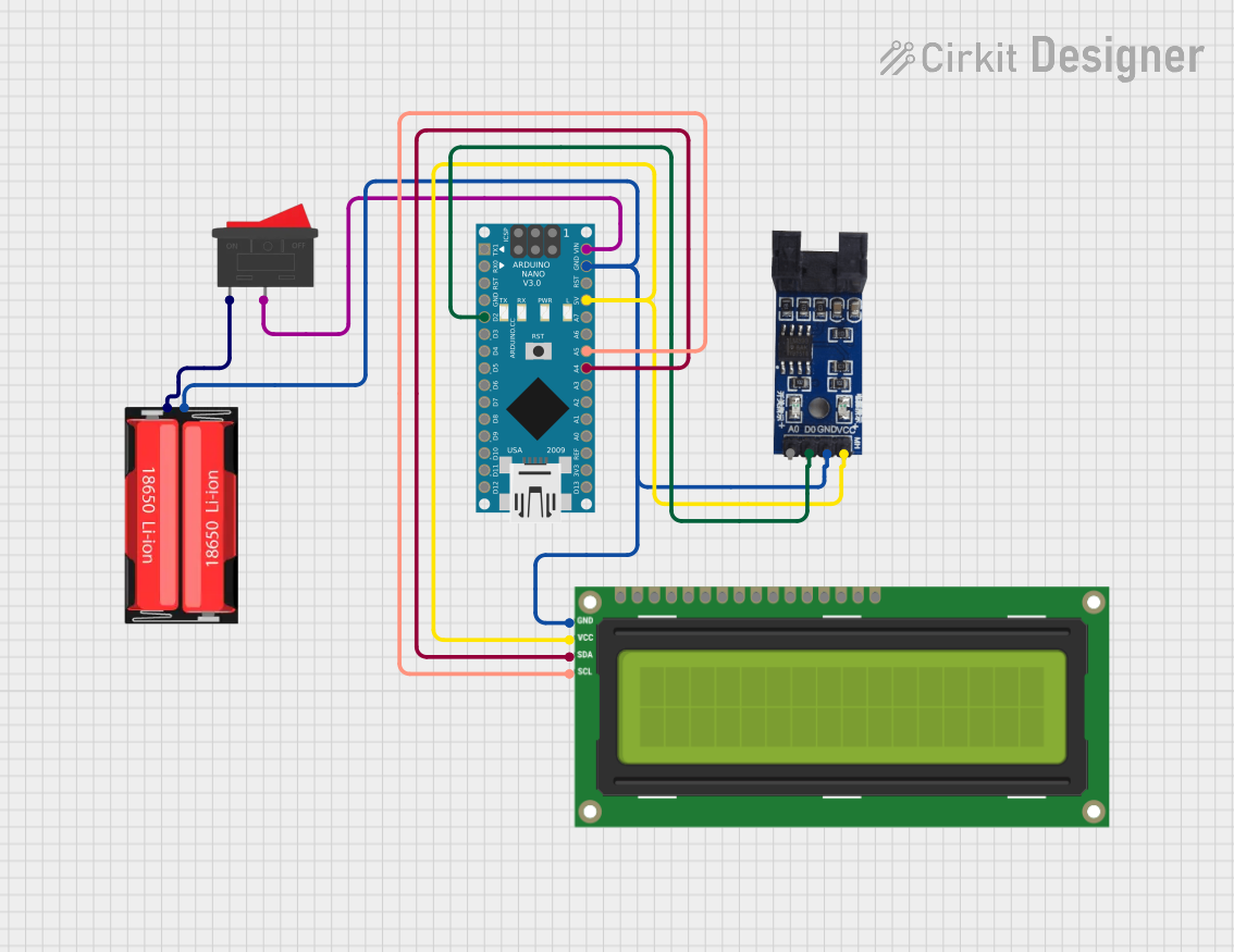
Explore Projects Built with Энкодер
Technical Specifications
Below are the key technical details for the Arduino Энкодер:
General Specifications
- Manufacturer: Arduino
- Part ID: Энкодер
- Type: Rotary Encoder
- Output: Digital (Quadrature signals: A and B)
- Supply Voltage: 3.3V to 5V DC
- Maximum Rotational Speed: 1000 RPM
- Resolution: 20 pulses per revolution (PPR)
- Operating Temperature: -10°C to 70°C
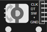
Pin Configuration and Descriptions
The Arduino Энкодер has 5 pins, as described in the table below:
| Pin Name | Type | Description |
|---|---|---|
| GND | Power | Ground connection for the encoder. |
| VCC | Power | Power supply input (3.3V to 5V DC). |
| A | Signal Output | Quadrature signal A, used to determine rotation direction and position. |
| B | Signal Output | Quadrature signal B, used in conjunction with signal A for position tracking. |
| SW | Signal Output | Push-button switch output, active LOW when the encoder knob is pressed. |
Usage Instructions
How to Use the Энкодер in a Circuit
Connect the Power Pins:
- Connect the
VCCpin to a 3.3V or 5V power source. - Connect the
GNDpin to the ground of your circuit.
- Connect the
Connect the Signal Pins:
- Connect the
AandBpins to two digital input pins on your microcontroller. These pins will read the quadrature signals to determine the encoder's position and direction. - Optionally, connect the
SWpin to another digital input pin to detect button presses.
- Connect the
Pull-Up Resistors:
- If your microcontroller does not have internal pull-up resistors, add external pull-up resistors (10kΩ) to the
A,B, andSWpins to ensure stable signal readings.
- If your microcontroller does not have internal pull-up resistors, add external pull-up resistors (10kΩ) to the
Write Code:
- Use the Arduino IDE to write a program that reads the encoder's signals and processes the data to track position, direction, or button presses.
Example Code for Arduino UNO
Below is an example code snippet to interface the Энкодер with an Arduino UNO:
// Define encoder pins
const int pinA = 2; // Connect to encoder pin A
const int pinB = 3; // Connect to encoder pin B
const int pinSW = 4; // Connect to encoder pin SW (button)

// Variables to track encoder state
volatile int encoderPosition = 0; // Tracks the encoder's position
int lastEncoded = 0; // Stores the last encoder state

void setup() {
  // Initialize serial communication
  Serial.begin(9600);

  // Configure encoder pins as inputs
  pinMode(pinA, INPUT);
  pinMode(pinB, INPUT);
  pinMode(pinSW, INPUT_PULLUP); // Enable internal pull-up for button

  // Attach interrupts to encoder pins
  attachInterrupt(digitalPinToInterrupt(pinA), updateEncoder, CHANGE);
  attachInterrupt(digitalPinToInterrupt(pinB), updateEncoder, CHANGE);
}

void loop() {
  // Print the encoder position to the serial monitor
  Serial.print("Encoder Position: ");
  Serial.println(encoderPosition);

  // Check if the button is pressed
  if (digitalRead(pinSW) == LOW) {
    Serial.println("Button Pressed!");
    delay(200); // Debounce delay
  }

  delay(100); // Small delay for readability
}

// Interrupt service routine to update encoder position
void updateEncoder() {
  int MSB = digitalRead(pinA); // Most significant bit
  int LSB = digitalRead(pinB); // Least significant bit

  int encoded = (MSB << 1) | LSB; // Combine A and B signals
  int sum = (lastEncoded << 2) | encoded; // Track state changes

  // Update position based on state transitions
  if (sum == 0b1101 || sum == 0b0100 || sum == 0b0010 || sum == 0b1011) {
    encoderPosition++;
  } else if (sum == 0b1110 || sum == 0b0111 || sum == 0b0001 || sum == 0b1000) {
    encoderPosition--;
  }

  lastEncoded = encoded; // Update last state
}
Important Considerations and Best Practices
- Debouncing: Mechanical encoders may produce noise or "bouncing" signals. Use software debouncing or hardware filters to ensure accurate readings.
- Interrupts: For high-speed applications, use hardware interrupts to handle encoder signals efficiently.
- Power Supply: Ensure the encoder's supply voltage matches the microcontroller's logic level to avoid damage.
- Mounting: Secure the encoder firmly to prevent misalignment or mechanical stress during operation.
Troubleshooting and FAQs
Common Issues and Solutions
Encoder Signals Are Unstable:
- Cause: Noise or lack of pull-up resistors.
- Solution: Add pull-up resistors to the
A,B, andSWpins. Use capacitors (e.g., 0.1µF) for noise filtering if necessary.
Incorrect Position Tracking:
- Cause: Missed pulses due to slow polling or improper interrupt handling.
- Solution: Use hardware interrupts for real-time signal processing.
Button Not Detected:
- Cause: Missing pull-up resistor or incorrect pin connection.
- Solution: Enable the internal pull-up resistor on the
SWpin or add an external pull-up resistor.
No Output from Encoder:
- Cause: Incorrect wiring or insufficient power supply.
- Solution: Double-check all connections and ensure the encoder is powered correctly.
FAQs
Q: Can I use the Энкодер with a 3.3V microcontroller?
A: Yes, the Энкодер is compatible with both 3.3V and 5V systems.Q: What is the maximum rotational speed the Энкодер can handle?
A: The Энкодер can handle speeds up to 1000 RPM.Q: How do I increase the resolution of the Энкодер?
A: The resolution is fixed at 20 PPR, but you can use software to interpolate signals for higher precision.Q: Can I use the Энкодер for motor speed control?
A: Yes, the Энкодер is suitable for motor speed and position control applications.
By following this documentation, you can effectively integrate the Arduino Энкодер into your projects for precise motion control and user input functionality.