How to Use MPU-6050: Examples, Pinouts, and Specs
Introduction
The MPU-6050 is a highly popular microelectromechanical systems (MEMS) sensor module that combines a 3-axis gyroscope and a 3-axis accelerometer. It measures motion in 6 degrees of freedom (6DoF), which makes it ideal for a wide range of applications including robotics, motion detection, and inertial measurement units (IMUs) for drones and other vehicles.
Explore Projects Built with MPU-6050

Explore Projects Built with MPU-6050
Technical Specifications
Key Features
- Gyroscope range: ±250, ±500, ±1000, ±2000 degrees/sec
- Accelerometer range: ±2g, ±4g, ±8g, ±16g
- Supply voltage: 2.3V to 3.4V
- Interface: I2C
- Digital-output temperature sensor
- Programmable interrupt
- Built-in 16-bit ADCs for digitizing the gyroscope and accelerometer outputs
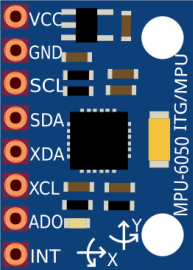
Pin Configuration
| Pin Number | Name | Description |
|---|---|---|
| 1 | VCC | Power supply (2.3V to 3.4V) |
| 2 | GND | Ground |
| 3 | SCL | I2C clock line |
| 4 | SDA | I2C data line |
| 5 | XDA | Auxiliary I2C data (optional) |
| 6 | XCL | Auxiliary I2C clock (optional) |
| 7 | AD0 | I2C address select (low: 0x68, high: 0x69) |
| 8 | INT | Interrupt output |
Usage Instructions
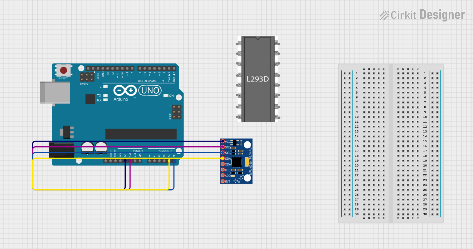
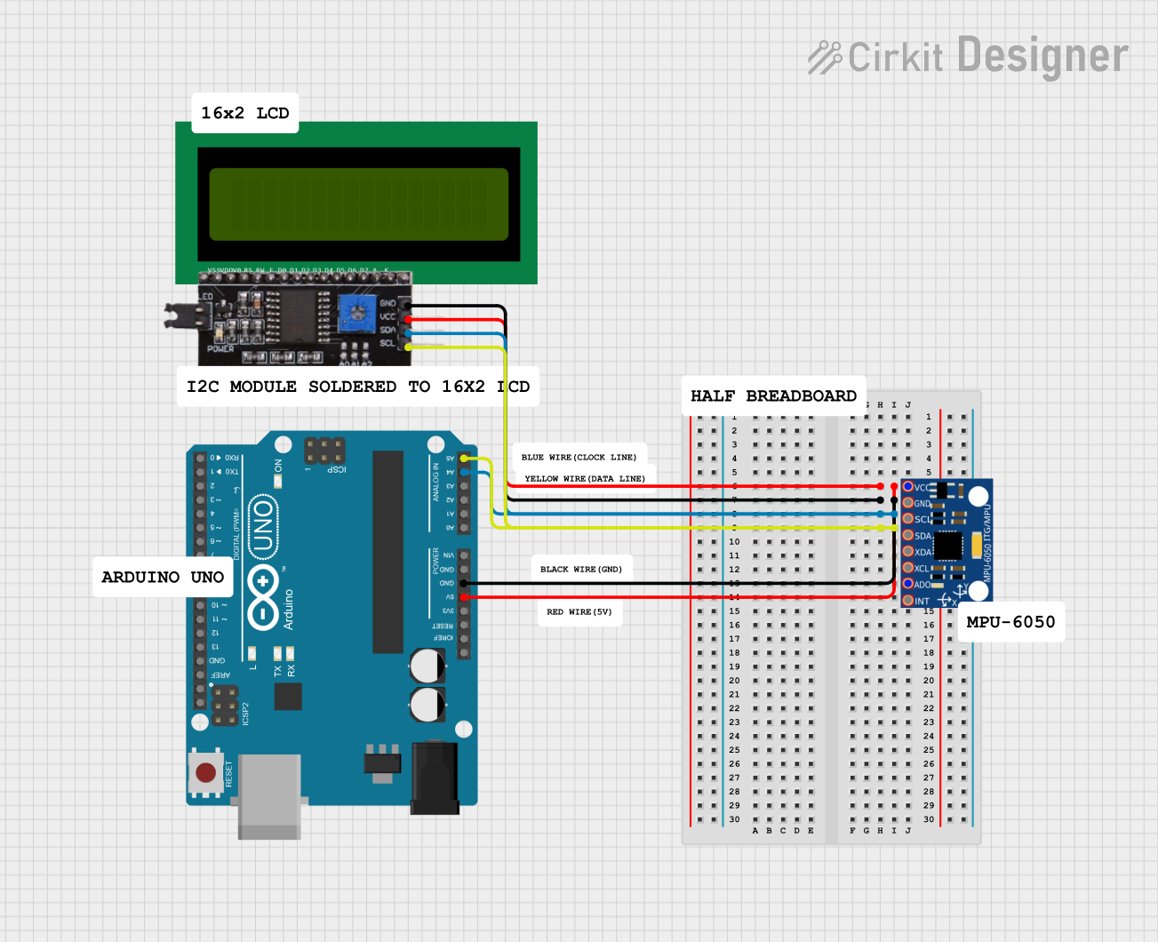
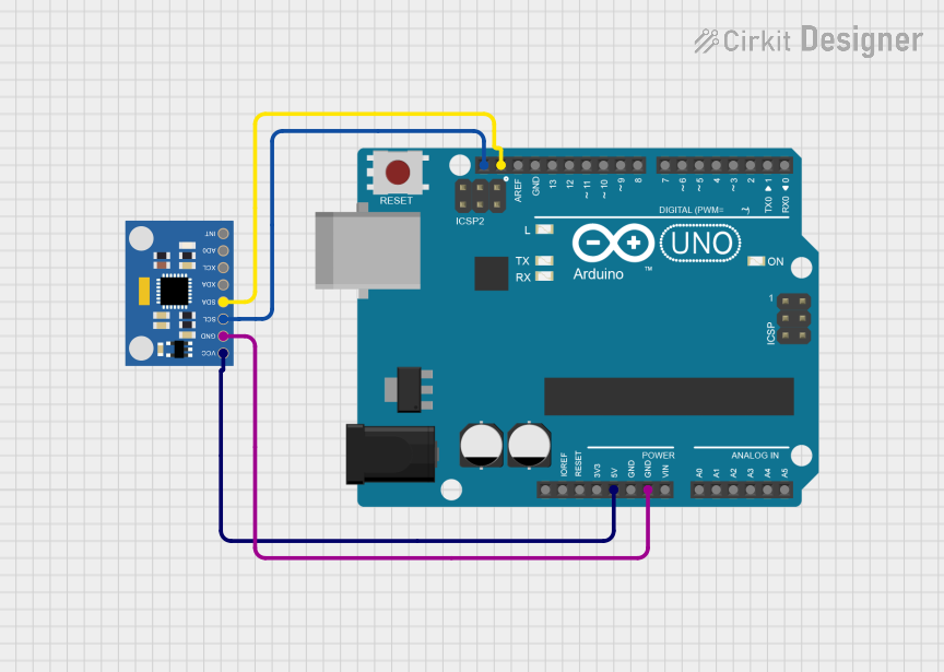
Integration with a Circuit
To use the MPU-6050 in a circuit:
- Connect VCC to a 2.3V to 3.4V power supply.
- Connect GND to the ground of the power supply.
- Connect SCL and SDA to the I2C clock and data lines, respectively.
- If using the auxiliary I2C bus, connect XDA and XCL accordingly.
- Set the AD0 pin to high or low to select the I2C address.
- The INT pin can be connected to an interrupt-capable GPIO on a microcontroller to handle sensor interrupts.
Best Practices
- Use pull-up resistors on the I2C lines (typically 4.7kΩ to 10kΩ).
- Ensure that the power supply is stable and within the specified voltage range.
- Avoid physical shocks and vibrations that could affect sensor readings.
- Calibrate the sensor for accurate measurements.
Example Code for Arduino UNO
#include <Wire.h>

// MPU-6050 I2C address (AD0 pin low)
const int MPU_ADDR = 0x68;

void setup() {
  Wire.begin(); // Initialize I2C communication
  Serial.begin(9600); // Start serial communication at 9600 baud
  Wire.beginTransmission(MPU_ADDR);
  Wire.write(0x6B); // PWR_MGMT_1 register
  Wire.write(0); // Set to zero to wake up the MPU-6050
  Wire.endTransmission(true);
}

void loop() {
  Wire.beginTransmission(MPU_ADDR);
  Wire.write(0x3B); // Starting register for accelerometer data
  Wire.endTransmission(false);
  Wire.requestFrom(MPU_ADDR, 14, true); // Request 14 bytes from MPU-6050

  // Read accelerometer and gyroscope data
  // Each value is a 16-bit signed integer (high byte first)
  int16_t accX = Wire.read() << 8 | Wire.read();
  int16_t accY = Wire.read() << 8 | Wire.read();
  int16_t accZ = Wire.read() << 8 | Wire.read();
  int16_t temp = Wire.read() << 8 | Wire.read();
  int16_t gyroX = Wire.read() << 8 | Wire.read();
  int16_t gyroY = Wire.read() << 8 | Wire.read();
  int16_t gyroZ = Wire.read() << 8 | Wire.read();

  // Print the sensor values
  Serial.print("Accelerometer: ");
  Serial.print("X = "); Serial.print(accX);
  Serial.print(" | Y = "); Serial.print(accY);
  Serial.print(" | Z = "); Serial.println(accZ);

  Serial.print("Gyroscope: ");
  Serial.print("X = "); Serial.print(gyroX);
  Serial.print(" | Y = "); Serial.print(gyroY);
  Serial.print(" | Z = "); Serial.println(gyroZ);

  // Print the temperature (in degrees Celsius)
  Serial.print("Temperature: ");
  Serial.print((temp / 340.00) + 36.53); // Formula from datasheet
  Serial.println(" C");

  delay(1000); // Delay a second for next reading
}
Troubleshooting and FAQs
Common Issues
- Inaccurate Readings: Ensure the sensor is calibrated properly. Avoid any vibrations or movements that are not part of the intended measurement.
- No Data on Serial Monitor: Check the wiring, especially the I2C connections. Ensure the correct I2C address is used in the code.
- Sensor Not Detected: Verify that the power supply is within the specified range and that the MPU-6050 is correctly powered.
FAQs
Q: Can the MPU-6050 be used with a 5V microcontroller like Arduino UNO? A: Yes, but ensure that the VCC is connected to a 3.3V output and use a level shifter or voltage divider for the SDA and SCL lines.
Q: How can I change the sensitivity of the accelerometer or gyroscope? A: You can write to the accelerometer and gyroscope configuration registers to set the desired full-scale range.
Q: What is the purpose of the AD0 pin? A: The AD0 pin is used to set the least significant bit (LSB) of the I2C address. This allows for two MPU-6050 sensors on the same I2C bus with different addresses.
Q: How do I calibrate the MPU-6050? A: Calibration involves taking multiple readings while the sensor is stationary and averaging them out to determine offsets. These offsets are then used to adjust the readings in the code.
This documentation provides an overview of the MPU-6050 sensor module, its technical specifications, usage instructions, example code for Arduino UNO, and troubleshooting tips. For more detailed information, refer to the manufacturer's datasheet and application notes.