
How to Use 4xAA Switchable Battery Pack w/JST connector: Examples, Pinouts, and Specs
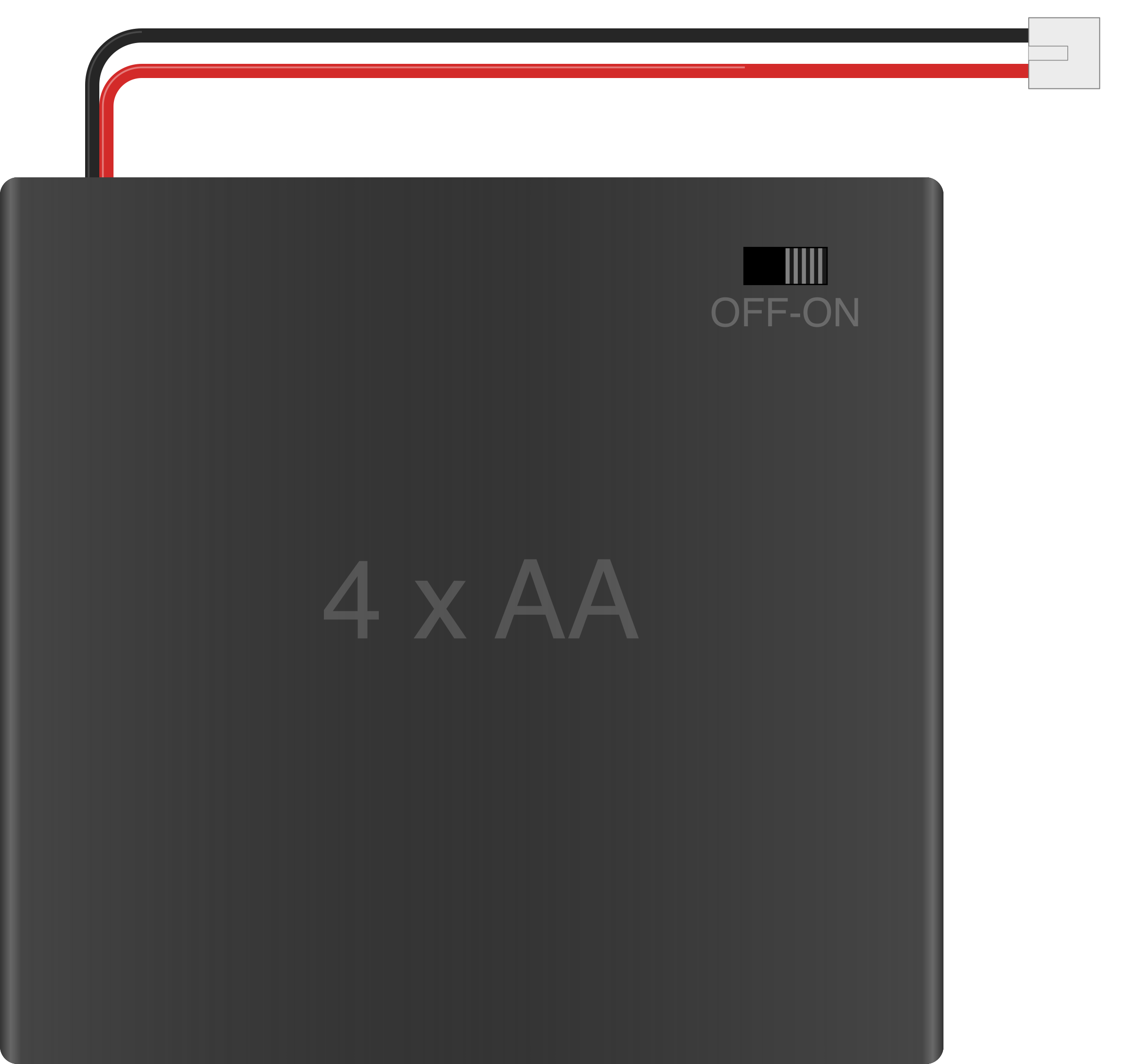
 Design with 4xAA Switchable Battery Pack w/JST connector in Cirkit Designer
Introduction
The 4xAA Switchable Battery Pack with JST connector is a compact and versatile power supply solution for electronic projects. It is designed to hold four AA batteries, providing a nominal output voltage of 6V (when using standard 1.5V alkaline batteries) or 4.8V (when using 1.2V rechargeable NiMH batteries). The built-in ON/OFF switch allows for convenient control of power delivery, while the JST connector ensures a secure and reliable connection to your circuit.
Explore Projects Built with 4xAA Switchable Battery Pack w/JST connector
 Open Project in Cirkit Designer
 Open Project in Cirkit Designer
 Open Project in Cirkit Designer
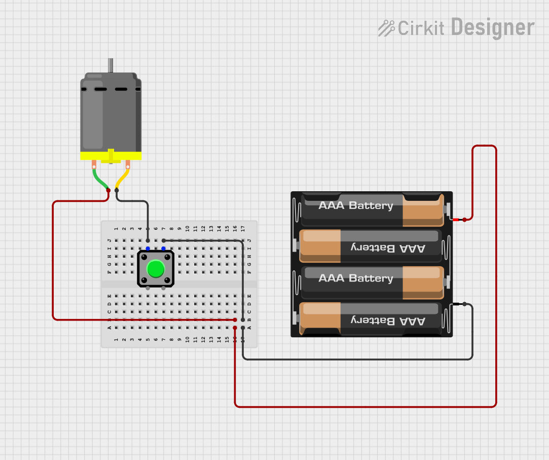 Open Project in Cirkit Designer
Explore Projects Built with 4xAA Switchable Battery Pack w/JST connector
Open Project in Cirkit DesignerOpen Project in Cirkit DesignerOpen Project in Cirkit DesignerOpen Project in Cirkit DesignerCommon Applications and Use Cases
- Powering small electronic devices and microcontroller projects
- Supplying portable power to Arduino, Raspberry Pi Pico, or similar boards
- Robotics and prototyping applications
- Educational and DIY electronics projects
Technical Specifications
Below are the key technical details of the 4xAA Switchable Battery Pack:
| Specification | Details |
|---|---|
| Battery Type | 4x AA (Alkaline or NiMH Rechargeable) |
| Nominal Output Voltage | 6V (Alkaline) / 4.8V (NiMH Rechargeable) |
| Maximum Output Current | Dependent on battery type (typically ~2A max) |
| Connector Type | JST PH 2.0mm 2-pin |
| Switch Type | Slide switch for ON/OFF control |
| Dimensions | ~65mm x 60mm x 20mm |
| Weight (without batteries) | ~30g |
Pin Configuration and Descriptions
The JST connector on the battery pack has two pins, as described below:
| Pin | Label | Description |
|---|---|---|
| 1 | V+ | Positive terminal of the battery pack (output voltage) |
| 2 | GND | Ground terminal of the battery pack |
Usage Instructions
How to Use the Component in a Circuit
- Insert Batteries: Open the battery compartment and insert four AA batteries, ensuring correct polarity as indicated inside the compartment.
- Connect to Circuit: Plug the JST connector into the corresponding JST socket on your circuit or device. Ensure the polarity matches (V+ to positive, GND to ground).
- Power ON/OFF: Use the slide switch to turn the battery pack ON or OFF as needed.
- Monitor Voltage: If using rechargeable batteries, ensure they are fully charged to provide optimal voltage.
Important Considerations and Best Practices
- Battery Type: Use high-quality AA batteries for reliable performance. Alkaline batteries provide higher voltage, while NiMH rechargeable batteries are more cost-effective for repeated use.
- Polarity: Always check the polarity of the JST connector before connecting to your circuit to avoid damage.
- Current Draw: Ensure the total current draw of your circuit does not exceed the maximum output current of the battery pack.
- Switch Usage: Turn the switch OFF when the battery pack is not in use to conserve battery life.
- Mounting: Secure the battery pack in your project to prevent accidental disconnection or damage.
Example: Connecting to an Arduino UNO
The 4xAA Switchable Battery Pack can be used to power an Arduino UNO via its VIN and GND pins. Below is an example wiring and code snippet:
Wiring:
- Connect the V+ pin of the JST connector to the VIN pin of the Arduino UNO.
- Connect the GND pin of the JST connector to the GND pin of the Arduino UNO.
Code Example:
// Example code to blink an LED using Arduino UNO powered by the 4xAA battery pack

const int ledPin = 13; // Pin connected to the built-in LED

void setup() {
  pinMode(ledPin, OUTPUT); // Set the LED pin as an output
}

void loop() {
  digitalWrite(ledPin, HIGH); // Turn the LED on
  delay(1000);               // Wait for 1 second
  digitalWrite(ledPin, LOW);  // Turn the LED off
  delay(1000);               // Wait for 1 second
}
Note: Ensure the total voltage from the battery pack (6V or 4.8V) is within the acceptable input voltage range of the Arduino UNO (7-12V recommended for VIN). If necessary, use a step-up converter to increase the voltage.
Troubleshooting and FAQs
Common Issues and Solutions
No Power Output:
- Ensure the batteries are inserted correctly with proper polarity.
- Verify that the slide switch is in the ON position.
- Check the battery charge level; replace or recharge batteries if needed.
Device Not Working:
- Confirm that the JST connector is securely plugged into the circuit.
- Check for proper polarity of the connection (V+ to positive, GND to ground).
Short Battery Life:
- Use high-capacity batteries for longer runtime.
- Turn the switch OFF when the battery pack is not in use.
Overheating:
- Ensure the current draw of your circuit does not exceed the battery pack's maximum output current.
- Inspect for short circuits in your wiring.
FAQs
Q: Can I use lithium AA batteries with this pack?
A: Yes, lithium AA batteries can be used, but ensure the total voltage does not exceed the input voltage rating of your circuit.
Q: Is the battery pack waterproof?
A: No, the battery pack is not waterproof. Avoid exposing it to moisture or water.
Q: Can I connect multiple battery packs in series or parallel?
A: Yes, but ensure the resulting voltage and current are compatible with your circuit and do not exceed the ratings of the components.
Q: How do I replace the JST connector if it gets damaged?
A: You can solder a new JST PH 2.0mm 2-pin connector to the wires, ensuring correct polarity.
By following this documentation, you can effectively use the 4xAA Switchable Battery Pack w/JST Connector in your electronic projects.