
How to Use DS1307 8-Pin PDIP RTC: Examples, Pinouts, and Specs
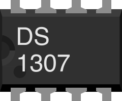
 Design with DS1307 8-Pin PDIP RTC in Cirkit Designer
Introduction
The DS1307 is a low-power, full binary-coded decimal (BCD) real-time clock (RTC) manufactured by Analog Devices / Maxim Integrated. It is designed to keep track of time and date information, including seconds, minutes, hours, day, date, month, and year, with leap year compensation valid up to 2100. The DS1307 operates using a 3V battery backup, ensuring timekeeping even during power outages. It communicates with microcontrollers via the I2C protocol, making it a versatile and widely used component in time-sensitive applications.
Explore Projects Built with DS1307 8-Pin PDIP RTC
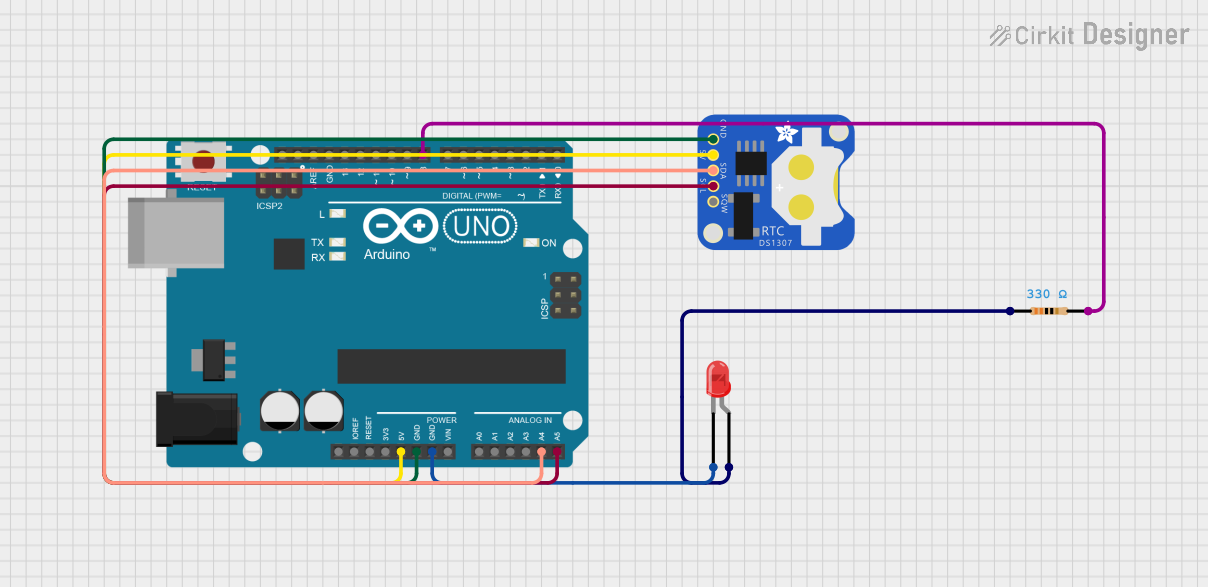 Open Project in Cirkit Designer
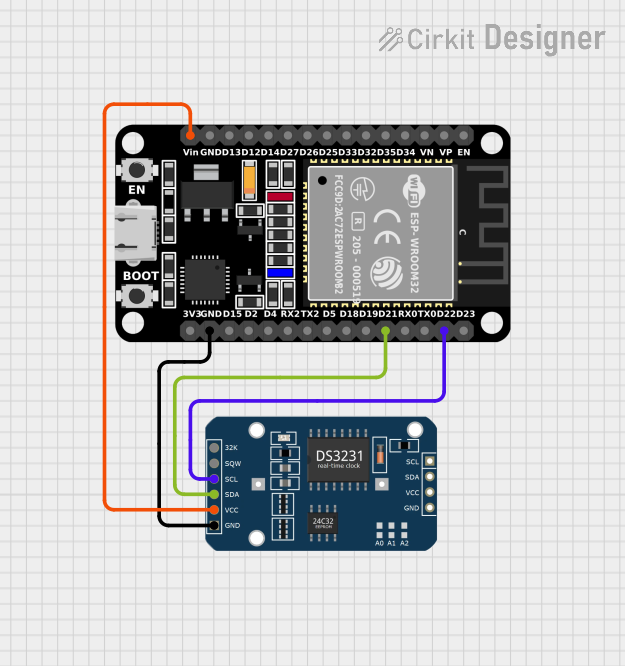 Open Project in Cirkit Designer
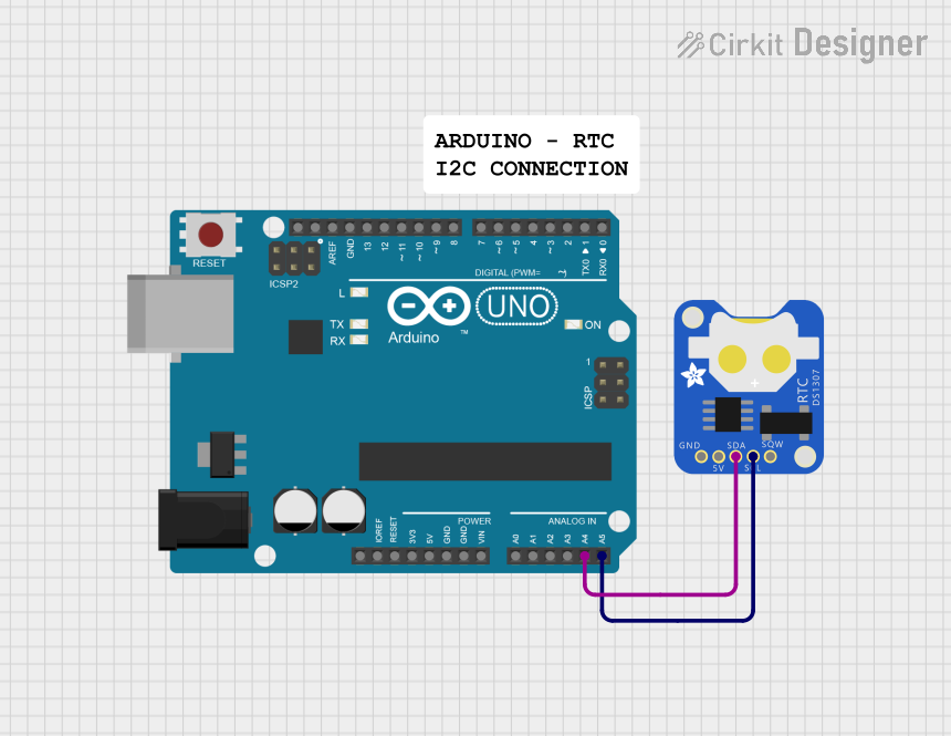 Open Project in Cirkit Designer
 Open Project in Cirkit Designer
Explore Projects Built with DS1307 8-Pin PDIP RTC
Open Project in Cirkit DesignerOpen Project in Cirkit DesignerOpen Project in Cirkit DesignerOpen Project in Cirkit DesignerCommon Applications
- Digital clocks and timers
- Data loggers
- Alarm systems
- Embedded systems requiring timekeeping
- Home automation systems
Technical Specifications
The DS1307 is a highly reliable RTC with the following key specifications:
| Parameter | Value |
|---|---|
| Supply Voltage (Vcc) | 4.5V to 5.5V |
| Backup Battery Voltage | 2.0V to 3.5V |
| Communication Protocol | I2C (Inter-Integrated Circuit) |
| Timekeeping Accuracy | ±2 seconds/day (at 25°C) |
| Operating Temperature | -40°C to +85°C |
| Package Type | 8-Pin PDIP |
| Oscillator Frequency | 32.768 kHz (external crystal) |
| Current Consumption | 300nA (with battery backup) |
Pin Configuration and Descriptions
The DS1307 comes in an 8-pin PDIP package. Below is the pinout and description:
| Pin Number | Pin Name | Description |
|---|---|---|
| 1 | X1 | Connection for the external 32.768 kHz crystal oscillator (input). |
| 2 | X2 | Connection for the external 32.768 kHz crystal oscillator (output). |
| 3 | VBAT | Backup battery input (2.0V to 3.5V). Maintains timekeeping during power loss. |
| 4 | GND | Ground connection. |
| 5 | SDA | Serial Data Line for I2C communication. |
| 6 | SCL | Serial Clock Line for I2C communication. |
| 7 | SQW/OUT | Square Wave/Output pin. Configurable for square wave output or logic level. |
| 8 | VCC | Primary power supply (4.5V to 5.5V). |
Usage Instructions
How to Use the DS1307 in a Circuit
- Power Supply: Connect the VCC pin to a 5V power source and the GND pin to ground. For backup power, connect a 3V coin cell battery to the VBAT pin.
- Crystal Oscillator: Attach a 32.768 kHz crystal oscillator between the X1 and X2 pins. No external capacitors are required.
- I2C Communication: Connect the SDA and SCL pins to the corresponding I2C pins on your microcontroller. Use pull-up resistors (typically 4.7kΩ) on both lines.
- Square Wave Output (Optional): If needed, configure the SQW/OUT pin to output a square wave signal or use it as a logic output.
Important Considerations
- Ensure the backup battery is properly connected to maintain timekeeping during power interruptions.
- Use a high-quality 32.768 kHz crystal oscillator for accurate timekeeping.
- Avoid placing the crystal oscillator near high-frequency components to minimize interference.
- Pull-up resistors are mandatory for the I2C lines (SDA and SCL) to function correctly.
Example Code for Arduino UNO
Below is an example of how to interface the DS1307 with an Arduino UNO using the Wire library:
#include <Wire.h>
#include <RTClib.h> // Include the Adafruit RTClib library for DS1307

RTC_DS1307 rtc; // Create an RTC object for DS1307

void setup() {
  Serial.begin(9600); // Initialize serial communication
  Wire.begin();       // Initialize I2C communication

  if (!rtc.begin()) {
    Serial.println("DS1307 not found. Check connections.");
    while (1); // Halt execution if RTC is not detected
  }

  if (!rtc.isrunning()) {
    Serial.println("RTC is not running. Setting the time...");
    rtc.adjust(DateTime(F(__DATE__), F(__TIME__)));
    // Set RTC to the current date and time from the computer
  }
}

void loop() {
  DateTime now = rtc.now(); // Get the current date and time

  // Print the current time in HH:MM:SS format
  Serial.print(now.hour());
  Serial.print(":");
  Serial.print(now.minute());
  Serial.print(":");
  Serial.println(now.second());

  delay(1000); // Wait for 1 second before updating
}
Notes:
- Install the Adafruit RTClib library in your Arduino IDE before using the code.
- The
rtc.adjust()function sets the RTC to the current system time. Use it only once or when resetting the clock.
Troubleshooting and FAQs
Common Issues
RTC Not Detected:
- Cause: Incorrect wiring or missing pull-up resistors on SDA and SCL lines.
- Solution: Verify connections and ensure 4.7kΩ pull-up resistors are present.
Incorrect Timekeeping:
- Cause: Faulty or low-quality crystal oscillator.
- Solution: Replace the crystal oscillator with a high-quality 32.768 kHz crystal.
RTC Resets After Power Loss:
- Cause: Backup battery not connected or discharged.
- Solution: Check the VBAT connection and replace the battery if necessary.
Square Wave Output Not Working:
- Cause: Incorrect configuration of the SQW/OUT pin.
- Solution: Use the appropriate I2C commands to configure the square wave output.
FAQs
Q1: Can the DS1307 operate without a backup battery?
A1: Yes, but it will lose timekeeping functionality during power interruptions.
Q2: What is the maximum I2C clock speed supported by the DS1307?
A2: The DS1307 supports I2C clock speeds up to 100 kHz.
Q3: Can I use the DS1307 with a 3.3V microcontroller?
A3: Yes, but you must use a level shifter for the I2C lines, as the DS1307 operates at 5V logic levels.
Q4: How long does the backup battery last?
A4: A typical CR2032 coin cell battery can last several years, depending on usage and temperature conditions.
This concludes the documentation for the DS1307 8-Pin PDIP RTC.