How to Use 2N7002 SOT23: Examples, Pinouts, and Specs
Introduction
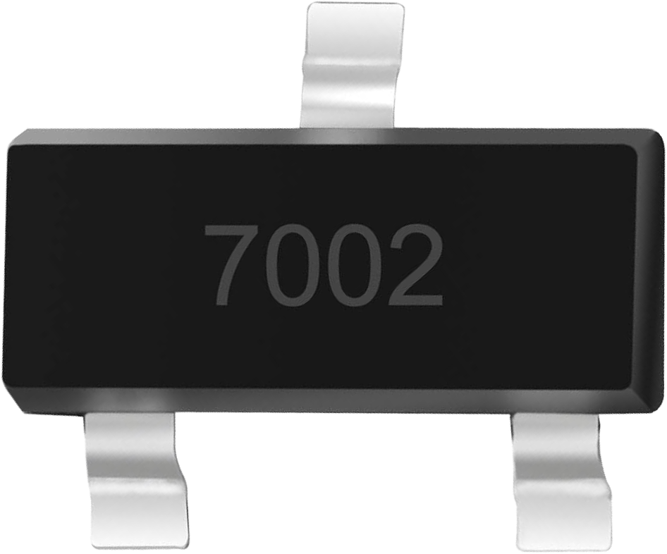
The 2N7002 is a small-signal N-channel MOSFET housed in a compact SOT-23 package. It is widely used in low-power switching applications due to its low on-resistance, fast switching speeds, and ease of integration into circuits. This MOSFET is ideal for applications such as driving small loads, level shifting, and interfacing logic-level signals with higher voltage circuits.
Explore Projects Built with 2N7002 SOT23

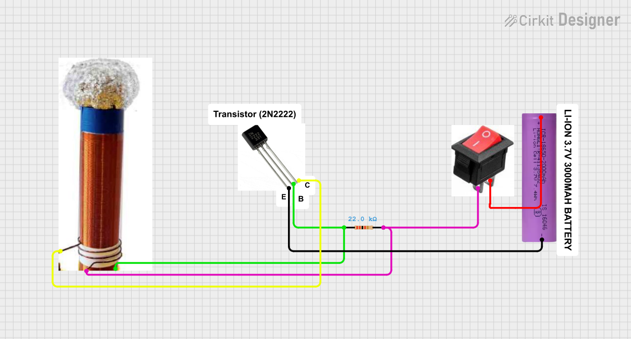

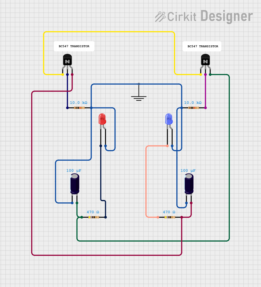
Explore Projects Built with 2N7002 SOT23
Common Applications
- Low-power switching circuits
- Signal level shifting
- Driving small relays, LEDs, or other low-current loads
- Logic-level interfacing
- General-purpose switching in embedded systems
Technical Specifications
The following table outlines the key technical specifications of the 2N7002 MOSFET:
| Parameter | Value |
|---|---|
| Type | N-channel MOSFET |
| Package | SOT-23 |
| Maximum Drain-Source Voltage (VDS) | 60V |
| Maximum Gate-Source Voltage (VGS) | ±20V |
| Continuous Drain Current (ID) | 200mA |
| Pulsed Drain Current (IDM) | 800mA |
| On-Resistance (RDS(on)) | 1.2Ω (at VGS = 10V, ID = 500mA) |
| Gate Threshold Voltage (VGS(th)) | 2.1V (typical) |
| Power Dissipation (PD) | 300mW |
| Operating Temperature Range | -55°C to +150°C |
Pin Configuration
The 2N7002 has three pins, as described in the table below:
| Pin Number | Pin Name | Description |
|---|---|---|
| 1 | Gate | Controls the MOSFET switching |
| 2 | Source | Connected to the source of current |
| 3 | Drain | Connected to the load or output |
Usage Instructions
How to Use the 2N7002 in a Circuit
Basic Circuit Setup:
- Connect the Source pin to ground or the negative terminal of the power supply.
- Connect the Drain pin to the load (e.g., an LED with a current-limiting resistor).
- Apply a voltage to the Gate pin to control the MOSFET. A voltage above the threshold (typically 2.1V) will turn the MOSFET on, allowing current to flow from the Drain to the Source.
Gate Resistor:
- Use a resistor (e.g., 10kΩ) between the Gate and ground to ensure the MOSFET remains off when no signal is applied to the Gate.
Driving with Logic Levels:
- The 2N7002 can be driven directly by 3.3V or 5V logic signals, making it compatible with microcontrollers like the Arduino UNO.
Example Circuit with Arduino UNO
Below is an example of using the 2N7002 to control an LED with an Arduino UNO:
Circuit Connections:
- Source: Connect to GND.
- Drain: Connect to one terminal of the LED. The other terminal of the LED should connect to a current-limiting resistor (e.g., 220Ω), which is then connected to +5V.
- Gate: Connect to an Arduino digital pin (e.g., pin 9) through a 220Ω resistor.
Arduino Code:
// Example code to control an LED using the 2N7002 MOSFET
const int mosfetGatePin = 9; // Pin connected to the Gate of the 2N7002

void setup() {
  pinMode(mosfetGatePin, OUTPUT); // Set the Gate pin as an output
}

void loop() {
  digitalWrite(mosfetGatePin, HIGH); // Turn on the MOSFET (LED ON)
  delay(1000); // Wait for 1 second
  digitalWrite(mosfetGatePin, LOW);  // Turn off the MOSFET (LED OFF)
  delay(1000); // Wait for 1 second
}
Important Considerations
- Voltage Levels: Ensure the Gate voltage (VGS) does not exceed ±20V to avoid damaging the MOSFET.
- Current Handling: Do not exceed the maximum continuous Drain current (200mA) to prevent overheating.
- Heat Dissipation: If the MOSFET operates near its maximum ratings, consider adding a heatsink or improving ventilation.
Troubleshooting and FAQs
Common Issues
MOSFET Not Switching:
- Ensure the Gate voltage exceeds the threshold voltage (VGS(th)).
- Check for proper connections and verify the Gate resistor is not too large.
Overheating:
- Verify that the Drain current does not exceed 200mA.
- Check for proper heat dissipation and ensure the MOSFET is not operating near its maximum power dissipation.
Load Not Turning On:
- Confirm the load is properly connected and functional.
- Verify the Gate signal is being applied correctly.
FAQs
Q: Can the 2N7002 be used for high-power applications?
A: No, the 2N7002 is designed for low-power applications with a maximum Drain current of 200mA. For high-power applications, consider using a power MOSFET.
Q: Is the 2N7002 compatible with 3.3V logic?
A: Yes, the 2N7002 can be driven by 3.3V logic signals, as its Gate threshold voltage is typically 2.1V.
Q: Do I need a Gate resistor?
A: While not strictly necessary, a Gate resistor (e.g., 220Ω) can help limit inrush current and protect the microcontroller driving the MOSFET.
Q: Can I use the 2N7002 for PWM control?
A: Yes, the 2N7002 is suitable for PWM applications due to its fast switching speeds.