How to Use MAX3485: Examples, Pinouts, and Specs
Introduction
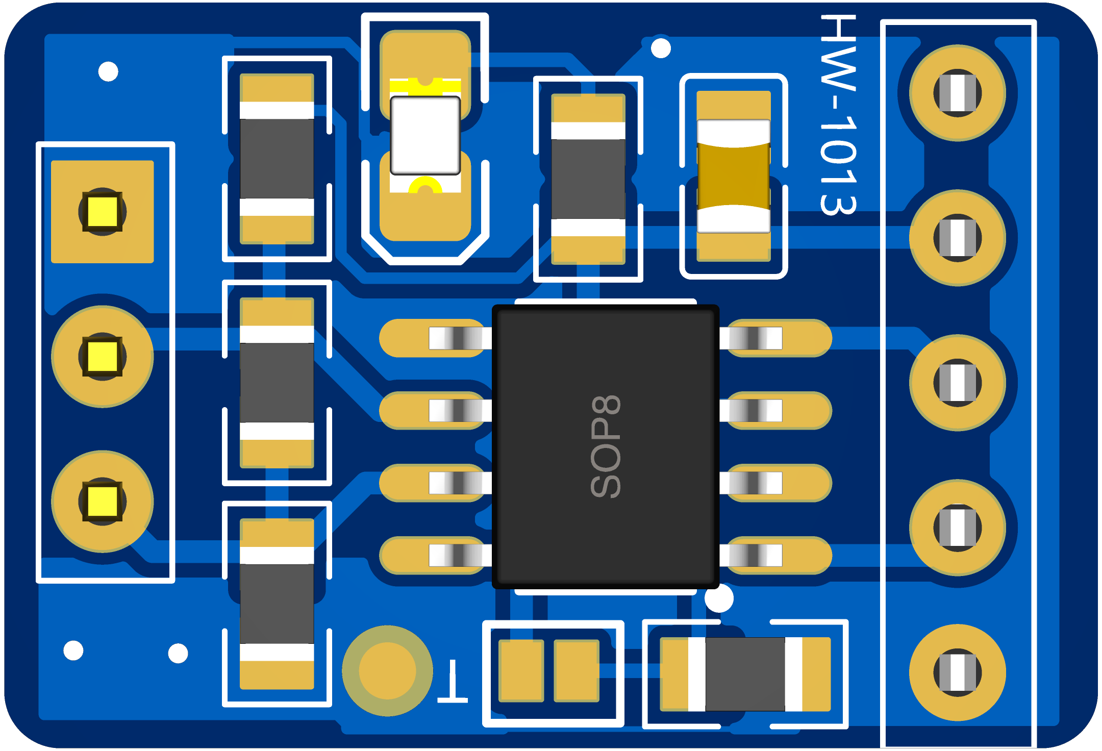
The MAX3485, manufactured by 宏维微 (part ID: HW-1013), is a low-power, half-duplex RS-485 transceiver designed for robust and reliable data communication over long distances. It supports high-speed data rates of up to 10 Mbps and operates over a wide voltage range, making it suitable for industrial and commercial communication systems. The MAX3485 is optimized for multipoint applications, allowing multiple devices to communicate on the same bus.
Explore Projects Built with MAX3485


Explore Projects Built with MAX3485
Common Applications
- Industrial automation and control systems
- Building automation (e.g., HVAC systems)
- Security and surveillance systems
- Point-of-sale (POS) terminals
- Data acquisition systems
- Long-distance communication networks
Technical Specifications
Key Technical Details
| Parameter | Value |
|---|---|
| Supply Voltage (Vcc) | 3.0V to 3.6V |
| Data Rate | Up to 10 Mbps |
| Communication Mode | Half-duplex |
| Input Voltage Range | -7V to +12V |
| Driver Output Voltage | -7V to +12V |
| Receiver Input Sensitivity | ±200 mV |
| Operating Temperature | -40°C to +85°C |
| Power Consumption | Low-power design (<1 µA in shutdown) |
| ESD Protection | ±15 kV (Human Body Model) |
Pin Configuration and Descriptions
The MAX3485 is typically available in an 8-pin SOIC package. Below is the pinout and description:
| Pin No. | Pin Name | Description |
|---|---|---|
| 1 | RO | Receiver Output: Outputs the received data signal. |
| 2 | RE̅ | Receiver Enable: Active-low input. Enables the receiver when low. |
| 3 | DE | Driver Enable: Active-high input. Enables the driver when high. |
| 4 | DI | Driver Input: Accepts the data to be transmitted. |
| 5 | GND | Ground: Connect to system ground. |
| 6 | A | Non-inverting Driver Output / Receiver Input (RS-485 bus line). |
| 7 | B | Inverting Driver Output / Receiver Input (RS-485 bus line). |
| 8 | Vcc | Power Supply: Connect to a 3.3V power source. |
Usage Instructions
How to Use the MAX3485 in a Circuit
- Power Supply: Connect the Vcc pin to a 3.3V power source and the GND pin to the system ground.
- Bus Connections: Connect the A and B pins to the RS-485 bus lines. Use termination resistors (typically 120Ω) at both ends of the bus for proper signal integrity.
- Driver and Receiver Control:
- To enable the driver, set the DE pin high.
- To enable the receiver, set the RE̅ pin low.
- For low-power operation, disable both the driver and receiver by setting DE low and RE̅ high.
- Data Transmission: Send data to the DI pin for transmission on the RS-485 bus. The received data will be output on the RO pin.
Important Considerations
- Termination Resistors: Always use termination resistors at both ends of the RS-485 bus to minimize signal reflections.
- Biasing Resistors: Use pull-up and pull-down resistors on the A and B lines to ensure a known idle state when no driver is active.
- ESD Protection: While the MAX3485 includes built-in ESD protection, consider adding external TVS diodes for additional protection in harsh environments.
- Bus Length and Data Rate: The maximum bus length decreases as the data rate increases. For long-distance communication, use lower data rates.
Example: Connecting the MAX3485 to an Arduino UNO
Below is an example of how to connect the MAX3485 to an Arduino UNO for RS-485 communication:
Circuit Connections
- MAX3485:
- Vcc → 3.3V on Arduino
- GND → GND on Arduino
- DI → Arduino TX (e.g., pin 1)
- RO → Arduino RX (e.g., pin 0)
- DE → Arduino digital pin (e.g., pin 2)
- RE̅ → Arduino digital pin (e.g., pin 3)
- A and B → RS-485 bus lines
Arduino Code
// RS-485 Communication Example with MAX3485
// Connect DE to pin 2 and RE̅ to pin 3 on the Arduino UNO

#define DE_PIN 2  // Driver Enable pin
#define RE_PIN 3  // Receiver Enable pin

void setup() {
  pinMode(DE_PIN, OUTPUT);  // Set DE as output
  pinMode(RE_PIN, OUTPUT);  // Set RE̅ as output

  // Enable receiver and disable driver initially
  digitalWrite(DE_PIN, LOW);
  digitalWrite(RE_PIN, LOW);

  Serial.begin(9600);  // Initialize serial communication
}

void loop() {
  // Example: Sending data
  digitalWrite(DE_PIN, HIGH);  // Enable driver
  digitalWrite(RE_PIN, HIGH);  // Disable receiver
  Serial.println("Hello, RS-485!");  // Send data
  delay(1000);  // Wait for 1 second

  // Example: Receiving data
  digitalWrite(DE_PIN, LOW);  // Disable driver
  digitalWrite(RE_PIN, LOW);  // Enable receiver
  if (Serial.available()) {
    String receivedData = Serial.readString();
    Serial.println("Received: " + receivedData);  // Print received data
  }
}
Troubleshooting and FAQs
Common Issues and Solutions
No Communication on the Bus:
- Ensure the DE and RE̅ pins are correctly controlled to enable the driver or receiver as needed.
- Verify that the A and B lines are properly connected and terminated with 120Ω resistors.
Data Corruption:
- Check for proper biasing resistors on the A and B lines to maintain a known idle state.
- Reduce the data rate if the bus length is too long.
Excessive Power Consumption:
- Ensure the device is in low-power mode (DE low, RE̅ high) when not actively transmitting or receiving.
Overheating:
- Verify that the supply voltage is within the specified range (3.0V to 3.6V).
- Check for short circuits on the A and B lines.
FAQs
Q: Can the MAX3485 be used in a full-duplex RS-485 system?
A: No, the MAX3485 is designed for half-duplex communication. For full-duplex systems, consider using a transceiver like the MAX3491.
Q: What is the maximum number of devices that can be connected to the RS-485 bus?
A: The MAX3485 supports up to 32 devices on the same bus.
Q: Can the MAX3485 operate at 5V?
A: No, the MAX3485 is designed for a supply voltage range of 3.0V to 3.6V. For 5V operation, consider using the MAX485.
Q: How do I protect the MAX3485 in an electrically noisy environment?
A: Use external TVS diodes and proper grounding techniques to enhance noise immunity and protect against voltage spikes.