Cirkit Designer
Your all-in-one circuit design IDE
Home /
Component Documentation
How to Use RS-485 to TTL Board: Examples, Pinouts, and Specs
Introduction
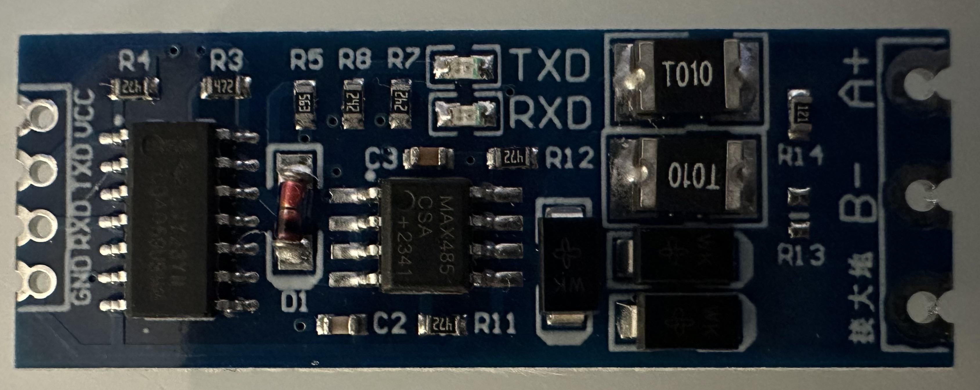
The RS-485 to TTL Board (Manufacturer Part ID: 2126) is a versatile module designed to convert RS-485 signals to TTL (Transistor-Transistor Logic) levels. This conversion enables seamless communication between devices operating at different voltage levels, making it an essential component in various electronic projects.
Explore Projects Built with RS-485 to TTL Board
Arduino UNO and Relay-Controlled RS485 Communication System

This circuit features an Arduino UNO microcontroller interfaced with a 4-channel relay module and a UART TTL to RS485 converter. The Arduino controls the relays via digital pins and communicates with the RS485 converter for serial communication, enabling control of external devices and communication over long distances.
Arduino UNO R4 WiFi and RS485 to TTL Interface Circuit with Pushbutton and LED Indicators
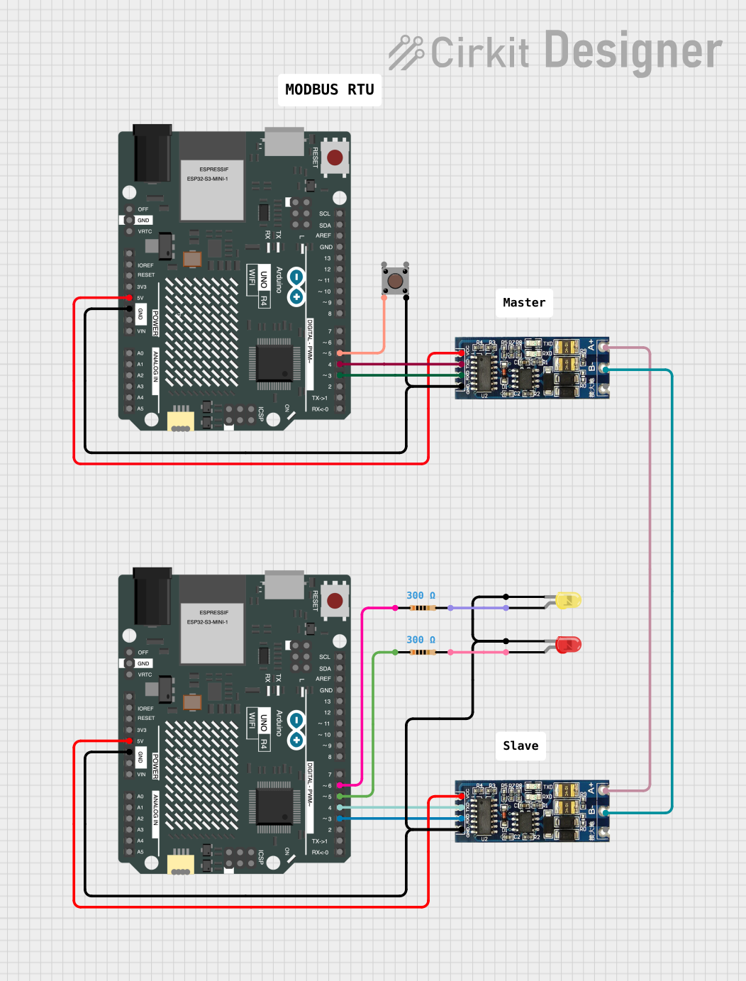
This circuit features two Arduino UNO R4 WiFi boards interfaced with RS485 to TTL converters, enabling serial communication over RS485 protocol. A pushbutton is connected to one of the Arduino boards, potentially to initiate communication or control actions. Additionally, there are two LEDs with series resistors, each connected to a separate Arduino, likely indicating the status or providing visual feedback for operations.
ESP32-Based Industrial Control System with RS485 Communication and I2C Interface

This circuit integrates a microcontroller with a display, digital potentiometer, IO expander, and opto-isolator board for signal interfacing and isolation. It includes a UART to RS485 converter for serial communication and a power converter to step down voltage for the system. The circuit is designed for control and communication in an isolated and protected environment.
STM32 and Arduino UNO Based Dual RS485 Communication Interface

This circuit consists of two microcontrollers, an STM32F103C8T6 and an Arduino UNO, each interfaced with separate RS485 transceiver modules for serial communication. The STM32F103C8T6 controls the RE (Receiver Enable) and DE (Driver Enable) pins of one RS485 module to manage its operation, and communicates via the A9 and A10 pins for DI (Data Input) and RO (Receiver Output), respectively. The Arduino UNO is similarly connected to another RS485 module, with digital pins D2 and D3 interfacing with DI and RO, and D8 controlling both RE and DE. The RS485 modules are connected to each other through their A and B differential communication lines, enabling serial data exchange between the two microcontrollers over a robust and long-distance capable RS485 network.
Explore Projects Built with RS-485 to TTL Board
Arduino UNO and Relay-Controlled RS485 Communication System
This circuit features an Arduino UNO microcontroller interfaced with a 4-channel relay module and a UART TTL to RS485 converter. The Arduino controls the relays via digital pins and communicates with the RS485 converter for serial communication, enabling control of external devices and communication over long distances.
Arduino UNO R4 WiFi and RS485 to TTL Interface Circuit with Pushbutton and LED Indicators
This circuit features two Arduino UNO R4 WiFi boards interfaced with RS485 to TTL converters, enabling serial communication over RS485 protocol. A pushbutton is connected to one of the Arduino boards, potentially to initiate communication or control actions. Additionally, there are two LEDs with series resistors, each connected to a separate Arduino, likely indicating the status or providing visual feedback for operations.
ESP32-Based Industrial Control System with RS485 Communication and I2C Interface
This circuit integrates a microcontroller with a display, digital potentiometer, IO expander, and opto-isolator board for signal interfacing and isolation. It includes a UART to RS485 converter for serial communication and a power converter to step down voltage for the system. The circuit is designed for control and communication in an isolated and protected environment.
STM32 and Arduino UNO Based Dual RS485 Communication Interface
This circuit consists of two microcontrollers, an STM32F103C8T6 and an Arduino UNO, each interfaced with separate RS485 transceiver modules for serial communication. The STM32F103C8T6 controls the RE (Receiver Enable) and DE (Driver Enable) pins of one RS485 module to manage its operation, and communicates via the A9 and A10 pins for DI (Data Input) and RO (Receiver Output), respectively. The Arduino UNO is similarly connected to another RS485 module, with digital pins D2 and D3 interfacing with DI and RO, and D8 controlling both RE and DE. The RS485 modules are connected to each other through their A and B differential communication lines, enabling serial data exchange between the two microcontrollers over a robust and long-distance capable RS485 network.
Common Applications and Use Cases
- Industrial Automation: Facilitates communication between industrial controllers and sensors.
- Home Automation: Connects home automation devices that use different communication protocols.
- Robotics: Enables communication between microcontrollers and motor drivers.
- Data Acquisition Systems: Integrates sensors and data loggers with different voltage requirements.
- Embedded Systems: Bridges communication between different embedded devices.
Technical Specifications
Key Technical Details
| Parameter | Value |
|---|---|
| Operating Voltage | 3.3V to 5V |
| Communication Type | RS-485 to TTL |
| Baud Rate | Up to 115200 bps |
| Operating Temperature | -40°C to 85°C |
| Dimensions | 44mm x 14mm x 11mm |
Pin Configuration and Descriptions
| Pin Number | Pin Name | Description |
|---|---|---|
| 1 | VCC | Power supply (3.3V to 5V) |
| 2 | GND | Ground |
| 3 | RO | Receiver Output (TTL level) |
| 4 | RE | Receiver Enable (Active Low) |
| 5 | DE | Driver Enable (Active High) |
| 6 | DI | Driver Input (TTL level) |
| 7 | A | RS-485 Line A |
| 8 | B | RS-485 Line B |
Usage Instructions
How to Use the Component in a Circuit
Power the Module:
- Connect the VCC pin to a 3.3V or 5V power supply.
- Connect the GND pin to the ground of your circuit.
Connect RS-485 Lines:
- Connect the A and B pins to the RS-485 bus lines.
Enable Communication:
- Connect the RE pin to ground to enable the receiver.
- Connect the DE pin to VCC to enable the driver.
Connect to Microcontroller:
- Connect the RO pin to the RX pin of your microcontroller.
- Connect the DI pin to the TX pin of your microcontroller.
Important Considerations and Best Practices
- Termination Resistor: Use a 120-ohm termination resistor between the A and B lines if the module is at the end of the RS-485 bus.
- Baud Rate Matching: Ensure that the baud rate of the RS-485 device matches the baud rate of the microcontroller.
- Noise Reduction: Keep the RS-485 lines as short as possible to reduce noise and signal degradation.
- Proper Grounding: Ensure a common ground between the RS-485 to TTL board and the microcontroller to avoid communication issues.
Example Code for Arduino UNO
#include <SoftwareSerial.h>

// Define the pins for the RS-485 to TTL module
#define RX_PIN 10
#define TX_PIN 11
#define RE_PIN 8
#define DE_PIN 9

// Create a SoftwareSerial object
SoftwareSerial rs485Serial(RX_PIN, TX_PIN);

void setup() {
  // Initialize the serial communication
  Serial.begin(9600);
  rs485Serial.begin(9600);

  // Set the RE and DE pins as outputs
  pinMode(RE_PIN, OUTPUT);
  pinMode(DE_PIN, OUTPUT);

  // Enable the receiver and disable the driver
  digitalWrite(RE_PIN, LOW);
  digitalWrite(DE_PIN, LOW);
}

void loop() {
  // Check if data is available on the RS-485 bus
  if (rs485Serial.available()) {
    // Read the data and print it to the Serial Monitor
    String data = rs485Serial.readString();
    Serial.println("Received: " + data);
  }

  // Check if data is available from the Serial Monitor
  if (Serial.available()) {
    // Read the data and send it over the RS-485 bus
    String data = Serial.readString();
    rs485Serial.println(data);

    // Enable the driver and disable the receiver
    digitalWrite(RE_PIN, HIGH);
    digitalWrite(DE_PIN, HIGH);

    // Wait for the data to be sent
    delay(10);

    // Disable the driver and enable the receiver
    digitalWrite(RE_PIN, LOW);
    digitalWrite(DE_PIN, LOW);
  }
}
Troubleshooting and FAQs
Common Issues Users Might Face
No Communication:
- Solution: Check the power connections and ensure the module is properly powered. Verify that the RE and DE pins are correctly set to enable communication.
Data Corruption:
- Solution: Ensure that the baud rates of the RS-485 device and the microcontroller match. Use a termination resistor if the module is at the end of the RS-485 bus.
Noise and Interference:
- Solution: Keep the RS-485 lines as short as possible and use twisted pair cables to reduce noise. Ensure proper grounding between devices.
Solutions and Tips for Troubleshooting
- Check Connections: Verify all connections, especially the power, ground, and communication lines.
- Use Serial Monitor: Utilize the Serial Monitor in the Arduino IDE to debug and monitor data transmission.
- Test with Known Good Devices: Test the RS-485 to TTL board with known good devices to isolate the issue.
By following this documentation, users can effectively integrate the RS-485 to TTL Board into their projects, ensuring reliable communication between devices with different voltage levels.