How to Use ESP-32 DEVKIT-V1 Expansion Board(with all pins): Examples, Pinouts, and Specs
Introduction
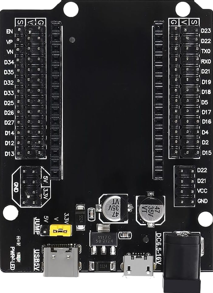
The ESP-32 DEVKIT-V1 Expansion Board, manufactured by Espressif, is a versatile development board designed for prototyping and building IoT (Internet of Things) applications. It features the powerful ESP32 chip, which integrates both Wi-Fi and Bluetooth capabilities, making it ideal for wireless communication projects. This board provides access to all GPIO pins, allowing seamless integration with various sensors, actuators, and modules.
Explore Projects Built with ESP-32 DEVKIT-V1 Expansion Board(with all pins)


Explore Projects Built with ESP-32 DEVKIT-V1 Expansion Board(with all pins)
Common Applications and Use Cases
- IoT devices and smart home automation
- Wireless sensor networks
- Wearable technology
- Robotics and automation systems
- Prototyping and educational projects
- Real-time data monitoring and logging
Technical Specifications
The ESP-32 DEVKIT-V1 Expansion Board is built around the ESP32 microcontroller, which is known for its high performance and low power consumption. Below are the key technical details:
Key Technical Details
| Parameter | Specification |
|---|---|
| Microcontroller | ESP32 (dual-core Xtensa LX6 processor) |
| Clock Speed | Up to 240 MHz |
| Flash Memory | 4 MB (varies by model) |
| SRAM | 520 KB |
| Wi-Fi | 802.11 b/g/n (2.4 GHz) |
| Bluetooth | Bluetooth 4.2 and BLE |
| Operating Voltage | 3.3V |
| Input Voltage (VIN) | 5V (via USB or external power supply) |
| GPIO Pins | 30+ (fully accessible) |
| ADC Channels | 18 (12-bit resolution) |
| DAC Channels | 2 (8-bit resolution) |
| Communication Interfaces | UART, SPI, I2C, I2S, PWM |
| Power Consumption | Ultra-low power modes available |
| Dimensions | 54 mm x 27 mm |
Pin Configuration and Descriptions
The ESP-32 DEVKIT-V1 Expansion Board provides access to all GPIO pins, which can be configured for various functions. Below is the pinout description:
| Pin Name | Functionality |
|---|---|
| VIN | Input voltage (5V) for powering the board |
| GND | Ground connection |
| 3V3 | 3.3V output for powering external components |
| EN | Enable pin (active high, used to reset the board) |
| IO0 | GPIO0 (used for boot mode selection during programming) |
| IO2 | GPIO2 (can be used as a general-purpose pin or for specific functions) |
| IO4 | GPIO4 (general-purpose pin) |
| IO5 | GPIO5 (general-purpose pin) |
| IO12 | GPIO12 (can be used as an ADC or general-purpose pin) |
| IO13 | GPIO13 (general-purpose pin, supports PWM) |
| IO14 | GPIO14 (general-purpose pin, supports PWM) |
| IO15 | GPIO15 (general-purpose pin, supports PWM) |
| IO16-39 | Additional GPIO pins with ADC, DAC, and other functionalities |
| TXD0 | UART0 Transmit (used for serial communication) |
| RXD0 | UART0 Receive (used for serial communication) |
| SCL | I2C Clock Line |
| SDA | I2C Data Line |
Note: Some GPIO pins have specific restrictions or are used during boot. Refer to the ESP32 datasheet for detailed pin behavior.
Usage Instructions
How to Use the ESP-32 DEVKIT-V1 in a Circuit
Powering the Board:
- Connect the board to your computer via a micro-USB cable for power and programming.
- Alternatively, supply 5V to the VIN pin and connect GND to the ground of your power source.
Programming the Board:
- Install the Arduino IDE and add the ESP32 board support package.
- Select "ESP32 Dev Module" from the Tools > Board menu.
- Connect the board to your computer and select the appropriate COM port.
- Write your code and upload it to the board.
Connecting Peripherals:
- Use jumper wires to connect sensors, actuators, or modules to the GPIO pins.
- Ensure that the voltage levels of connected components are compatible with the 3.3V logic of the ESP32.
Using Wi-Fi and Bluetooth:
- Use the built-in libraries (
WiFi.handBluetoothSerial.h) to enable wireless communication. - Configure the ESP32 as a Wi-Fi client, access point, or Bluetooth device as needed.
- Use the built-in libraries (
Important Considerations and Best Practices
- Voltage Levels: The GPIO pins operate at 3.3V. Avoid connecting 5V signals directly to the pins to prevent damage.
- Boot Mode: GPIO0 must be pulled low during programming. Ensure no external components interfere with this pin.
- Power Supply: Use a stable power source to avoid unexpected resets or instability.
- Heat Management: The ESP32 can get warm during operation. Ensure proper ventilation if used in an enclosed space.
Example Code for Arduino IDE
The following example demonstrates how to connect the ESP-32 DEVKIT-V1 to a Wi-Fi network and print the IP address:
#include <WiFi.h> // Include the Wi-Fi library

const char* ssid = "Your_SSID";       // Replace with your Wi-Fi network name
const char* password = "Your_Password"; // Replace with your Wi-Fi password

void setup() {
  Serial.begin(115200); // Initialize serial communication at 115200 baud
  delay(1000);          // Wait for a moment to stabilize

  Serial.println("Connecting to Wi-Fi...");
  WiFi.begin(ssid, password); // Start connecting to Wi-Fi

  while (WiFi.status() != WL_CONNECTED) {
    delay(500); // Wait until the connection is established
    Serial.print(".");
  }

  Serial.println("\nConnected to Wi-Fi!");
  Serial.print("IP Address: ");
  Serial.println(WiFi.localIP()); // Print the assigned IP address
}

void loop() {
  // Add your main code here
}
Tip: Replace
Your_SSIDandYour_Passwordwith your Wi-Fi credentials before uploading the code.
Troubleshooting and FAQs
Common Issues and Solutions
The board is not detected by the computer:
- Ensure the USB cable is functional and supports data transfer.
- Install the required USB-to-serial driver (e.g., CP2102 or CH340, depending on your board).
Upload fails with a timeout error:
- Press and hold the "BOOT" button on the board while uploading the code.
- Check that the correct COM port and board type are selected in the Arduino IDE.
Wi-Fi connection fails:
- Verify the SSID and password in your code.
- Ensure the Wi-Fi network is within range and not using unsupported security protocols.
GPIO pins not working as expected:
- Check if the pin is reserved for boot or other special functions.
- Avoid using GPIO6-GPIO11, as they are connected to the onboard flash memory.
FAQs
Can I power the board with a battery?
Yes, you can use a 3.7V LiPo battery connected to the 3V3 pin or a 5V source connected to the VIN pin.What is the maximum current output of the 3.3V pin?
The 3.3V pin can supply up to 500 mA, depending on the input power source.Can I use the ESP32 with MicroPython?
Yes, the ESP32 supports MicroPython. You can flash the MicroPython firmware to the board and use it for programming.Is the board compatible with Arduino libraries?
Most Arduino libraries are compatible with the ESP32. However, some may require modifications for full functionality.