Cirkit Designer Logo
Cirkit Designer
Your all-in-one circuit design IDE
Home / 
Component Documentation

How to Use TP4056 Battery Charging Protection Module (Type C): Examples, Pinouts, and Specs

Image of TP4056 Battery Charging Protection Module (Type C)
Cirkit Designer LogoDesign with TP4056 Battery Charging Protection Module (Type C) in Cirkit Designer

Introduction

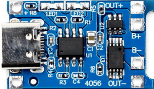
The TP4056 Battery Charging Protection Module (Type C) is a compact, highly integrated solution for charging and protecting single-cell lithium-ion or lithium polymer batteries. It is equipped with a USB Type-C input port and is designed for portable electronic devices, such as power banks, DIY electronics projects, and any application that requires battery management. The module's built-in protection features safeguard the battery from overcharging, over-discharging, and overcurrent conditions, ensuring safe and reliable operation.

Explore Projects Built with TP4056 Battery Charging Protection Module (Type C)

Use Cirkit Designer to design, explore, and prototype these projects online. Some projects support real-time simulation. Click "Open Project" to start designing instantly!
Battery-Powered 18650 Li-ion Charger with USB Output and Adjustable Voltage Regulator
Image of Breadboard: A project utilizing TP4056 Battery Charging Protection Module (Type C) in a practical application
This circuit is a battery management and power supply system that uses three 3.7V batteries connected to a 3S 10A Li-ion 18650 Charger Protection Board Module for balanced charging and protection. The system includes a TP4056 Battery Charging Protection Module for additional charging safety, a Step Up Boost Power Converter to regulate and boost the voltage, and a USB regulator to provide a stable 5V output, controlled by a push switch.
Cirkit Designer LogoOpen Project in Cirkit Designer
Solar-Powered Battery Charging and Monitoring System with TP4056 and 7-Segment Voltmeter
Image of CKT: A project utilizing TP4056 Battery Charging Protection Module (Type C) in a practical application
This circuit is a solar-powered battery charging and monitoring system. It uses a TP4056 module to charge a Li-ion 18650 battery from solar cells and a DC generator, with multiple LEDs and a voltmeter to indicate the charging status and battery voltage. The circuit also includes transistors and resistors to control the LEDs and a bridge rectifier for AC to DC conversion.
Cirkit Designer LogoOpen Project in Cirkit Designer
ESP32-Based Battery-Powered Multi-Sensor System
Image of Dive sense: A project utilizing TP4056 Battery Charging Protection Module (Type C) in a practical application
This circuit consists of a TP4056 module connected to a 3.7V LiPo battery, providing a charging interface for the battery. The TP4056 manages the charging process by connecting its B+ and B- pins to the battery's positive and ground terminals, respectively.
Cirkit Designer LogoOpen Project in Cirkit Designer
Solar-Powered ESP32 DC Voltmeter with Wi-Fi and LCD Display
Image of ietp: A project utilizing TP4056 Battery Charging Protection Module (Type C) in a practical application
This circuit is a solar-powered battery charging and monitoring system. It uses a TP4056 module to charge a 18650 battery from a solar panel, and an ESP32 microcontroller to monitor the battery voltage and display it on an I2C LCD, while also sending the data to a Blynk application for remote monitoring.
Cirkit Designer LogoOpen Project in Cirkit Designer

Explore Projects Built with TP4056 Battery Charging Protection Module (Type C)

Use Cirkit Designer to design, explore, and prototype these projects online. Some projects support real-time simulation. Click "Open Project" to start designing instantly!
Image of Breadboard: A project utilizing TP4056 Battery Charging Protection Module (Type C) in a practical application
Battery-Powered 18650 Li-ion Charger with USB Output and Adjustable Voltage Regulator
This circuit is a battery management and power supply system that uses three 3.7V batteries connected to a 3S 10A Li-ion 18650 Charger Protection Board Module for balanced charging and protection. The system includes a TP4056 Battery Charging Protection Module for additional charging safety, a Step Up Boost Power Converter to regulate and boost the voltage, and a USB regulator to provide a stable 5V output, controlled by a push switch.
Cirkit Designer LogoOpen Project in Cirkit Designer
Image of CKT: A project utilizing TP4056 Battery Charging Protection Module (Type C) in a practical application
Solar-Powered Battery Charging and Monitoring System with TP4056 and 7-Segment Voltmeter
This circuit is a solar-powered battery charging and monitoring system. It uses a TP4056 module to charge a Li-ion 18650 battery from solar cells and a DC generator, with multiple LEDs and a voltmeter to indicate the charging status and battery voltage. The circuit also includes transistors and resistors to control the LEDs and a bridge rectifier for AC to DC conversion.
Cirkit Designer LogoOpen Project in Cirkit Designer
Image of Dive sense: A project utilizing TP4056 Battery Charging Protection Module (Type C) in a practical application
ESP32-Based Battery-Powered Multi-Sensor System
This circuit consists of a TP4056 module connected to a 3.7V LiPo battery, providing a charging interface for the battery. The TP4056 manages the charging process by connecting its B+ and B- pins to the battery's positive and ground terminals, respectively.
Cirkit Designer LogoOpen Project in Cirkit Designer
Image of ietp: A project utilizing TP4056 Battery Charging Protection Module (Type C) in a practical application
Solar-Powered ESP32 DC Voltmeter with Wi-Fi and LCD Display
This circuit is a solar-powered battery charging and monitoring system. It uses a TP4056 module to charge a 18650 battery from a solar panel, and an ESP32 microcontroller to monitor the battery voltage and display it on an I2C LCD, while also sending the data to a Blynk application for remote monitoring.
Cirkit Designer LogoOpen Project in Cirkit Designer

Technical Specifications

Key Technical Details

  • Input Voltage (VIN): 4.5V to 5.5V
  • Charge Current (ICHG): Programmable up to 1A via resistor
  • Battery Voltage (VBAT): 4.2V precision charging voltage
  • Operating Temperature: -10°C to +85°C
  • Charging Indicator: LED status for charging and full charge
  • Protection Features: Overcharge, over-discharge, and overcurrent protection

Pin Configuration and Descriptions

Pin Number Pin Name Description
1 B+ Battery positive terminal
2 B- Battery negative terminal
3 OUT+ Output positive terminal
4 OUT- Output negative terminal
5 IN+ USB Type-C positive input
6 IN- USB Type-C negative input

Usage Instructions

How to Use the Component in a Circuit

  1. Connecting the Battery:

    • Connect the positive terminal of the battery to the B+ pin.
    • Connect the negative terminal of the battery to the B- pin.
  2. Power Supply:

    • Connect a 5V power supply to the USB Type-C input (IN+ and IN- pins).
  3. Load Connection:

    • Connect the load to the OUT+ and OUT- pins.
  4. Charging:

    • When the module is powered via USB Type-C, the charging process starts automatically if the battery voltage is below 4.2V.
    • The charging status is indicated by the onboard LED.

Important Considerations and Best Practices

  • Input Voltage: Ensure that the input voltage does not exceed the specified range to prevent damage to the module.
  • Current Rating: Do not exceed the maximum charging current of 1A; select an appropriate resistor to set the desired charging current.
  • Heat Dissipation: Provide adequate ventilation around the module as it may generate heat during operation.
  • Battery Type: Use the module only with lithium-ion or lithium polymer batteries.
  • Protection: Do not disable the onboard protection features as they are critical for battery safety.

Troubleshooting and FAQs

Common Issues

  • LED Not Lighting Up: Ensure the power supply is connected correctly and the battery is properly seated.
  • Battery Not Charging: Check the battery connections and verify that the battery is not already fully charged or damaged.
  • Module Overheating: Reduce the charging current if the module is too hot during operation.

Solutions and Tips for Troubleshooting

  • Check Connections: Verify all connections are secure and correct.
  • Inspect Battery: Ensure the battery is in good condition and compatible with the module.
  • Current Setting: Confirm the charging current is set correctly for your battery.

FAQs

Q: Can I charge multiple batteries with this module? A: No, the TP4056 is designed for single-cell lithium-ion or lithium polymer batteries.

Q: What should I do if the module gets too hot? A: Reduce the charging current, ensure proper ventilation, and check for any shorts or excessive load on the output.

Q: How do I know when the battery is fully charged? A: The onboard LED will change its status, typically turning off or changing color, to indicate a full charge.

Example Code for Arduino UNO

// There is no direct interaction code for the TP4056 with Arduino as it is a standalone charging module.
// However, you can monitor the battery voltage using Arduino's ADC.

const int batteryPin = A0; // Connect battery to A0 through a voltage divider

void setup() {
  Serial.begin(9600);
}

void loop() {
  int sensorValue = analogRead(batteryPin);
  float voltage = sensorValue * (5.0 / 1023.0); // Convert the reading to voltage
  Serial.print("Battery Voltage: ");
  Serial.println(voltage);
  delay(1000); // Wait for a second between readings
}

Note: When measuring battery voltage, ensure that the voltage at the analog pin does not exceed 5V. Use a voltage divider if necessary to bring the voltage within a safe range for the Arduino ADC.