How to Use Do Sensor: Examples, Pinouts, and Specs
Introduction
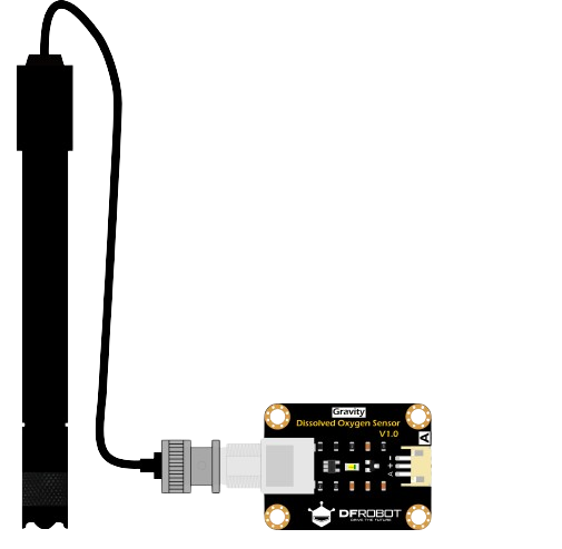
A Do Sensor is a versatile electronic component designed to detect and measure specific physical properties or environmental conditions. It is commonly used in automation and control systems to provide real-time feedback for decision-making processes. These sensors are integral to applications such as environmental monitoring, industrial automation, and smart home systems. Their ability to deliver accurate and reliable data makes them a critical component in modern electronics.
Explore Projects Built with Do Sensor
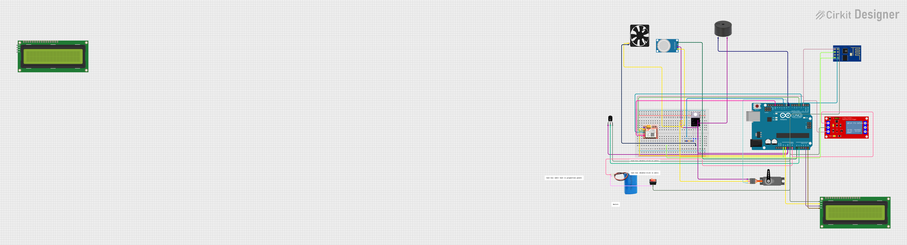
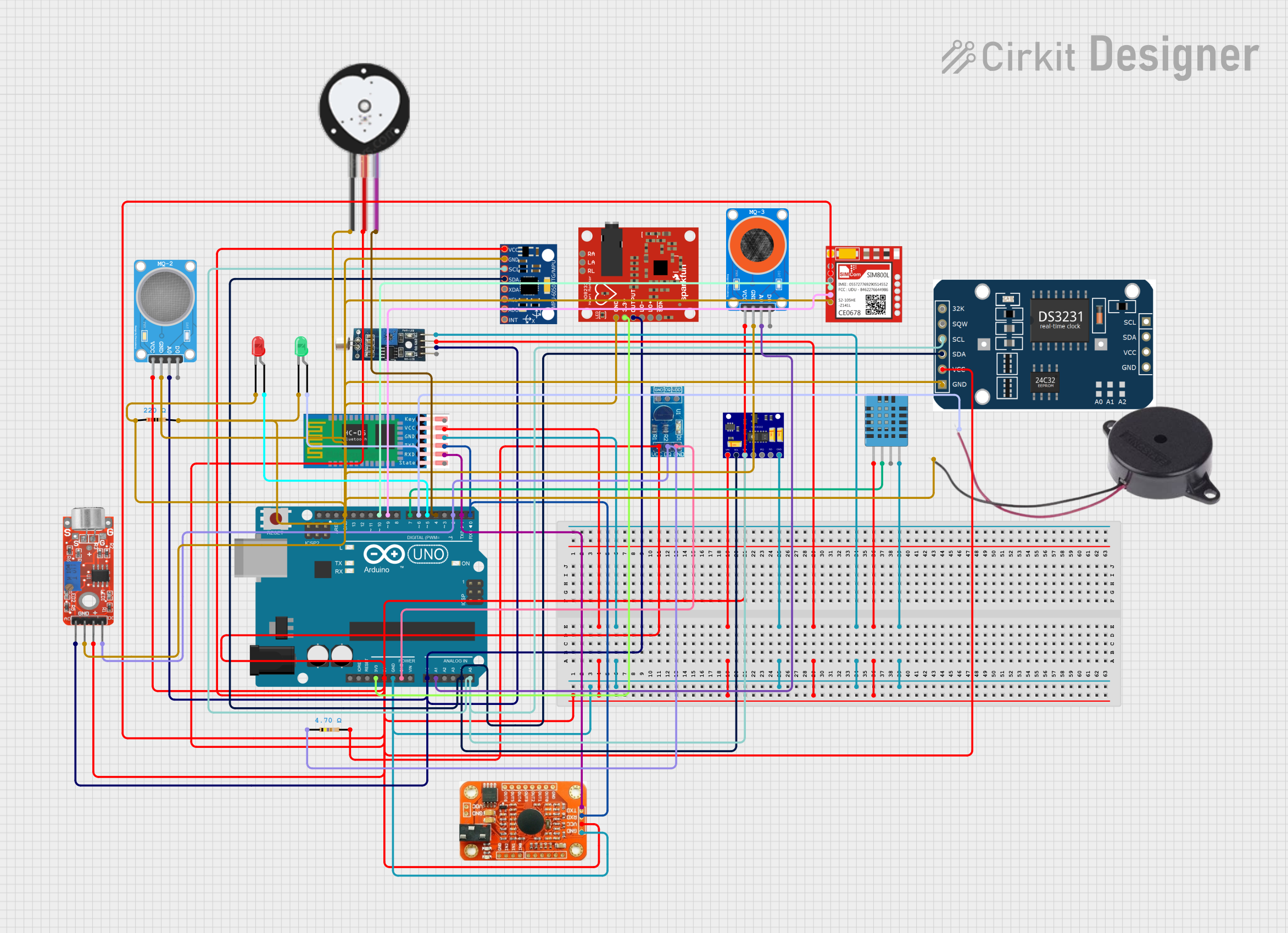

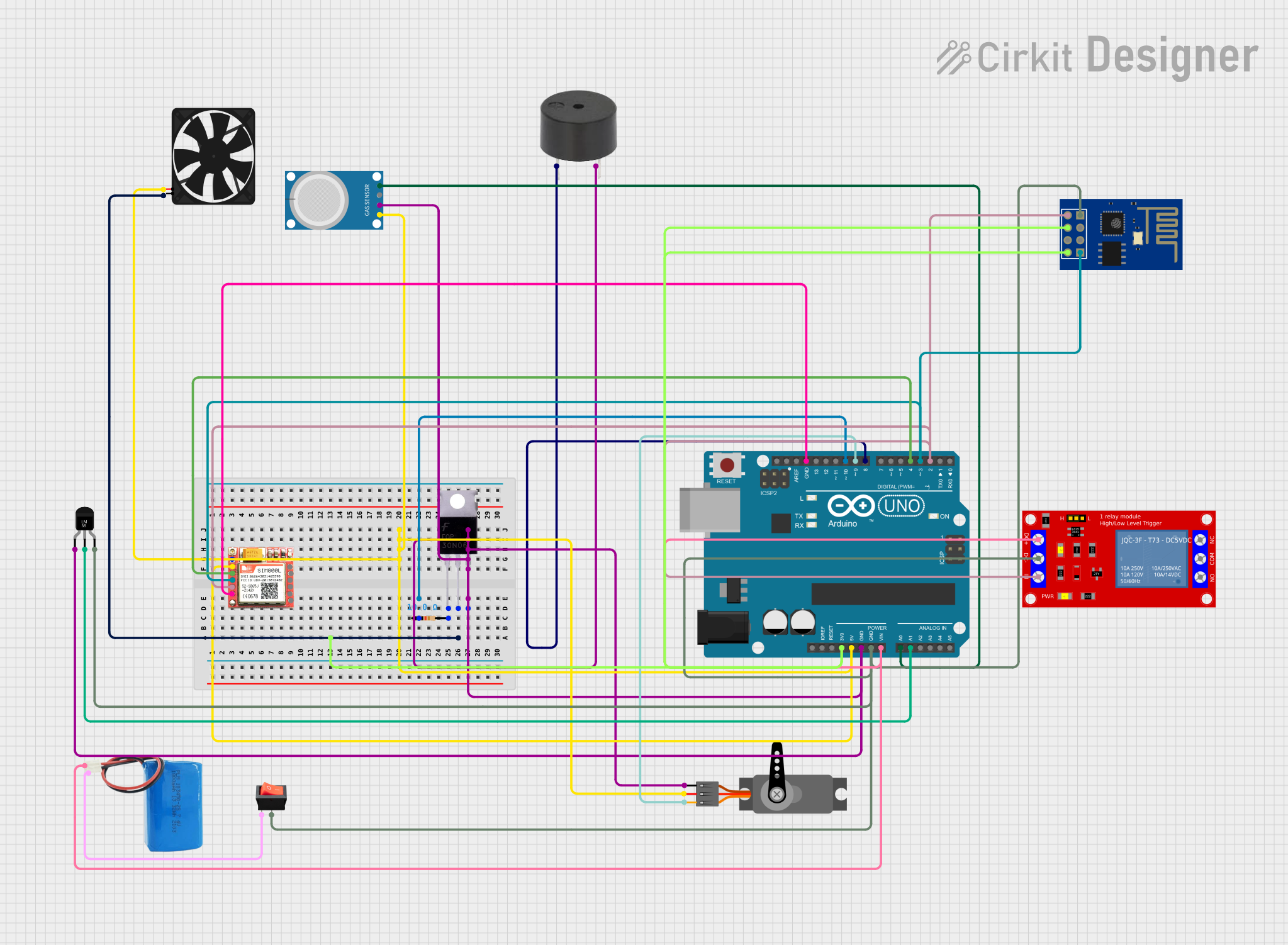
Explore Projects Built with Do Sensor
Technical Specifications
The technical specifications of a Do Sensor can vary depending on the specific type and model. Below are general specifications for a typical Do Sensor:
- Operating Voltage: 3.3V to 5V
- Output Signal: Analog or Digital (depending on the model)
- Measurement Range: Varies based on the sensor type (e.g., temperature, humidity, etc.)
- Response Time: Typically < 1 second
- Operating Temperature: -10°C to 50°C
- Accuracy: ±2% (varies by model)
Pin Configuration and Descriptions
The Do Sensor typically has three or more pins. Below is a standard pinout configuration:
| Pin Name | Description |
|---|---|
| VCC | Power supply input (3.3V to 5V) |
| GND | Ground connection |
| OUT | Output signal (Analog or Digital) |
For models with additional features, there may be extra pins:
| Pin Name | Description |
|---|---|
| A0 | Analog output signal |
| D0 | Digital output signal |
| CAL | Calibration pin (if applicable) |
Usage Instructions
How to Use the Do Sensor in a Circuit
- Power the Sensor: Connect the VCC pin to a 3.3V or 5V power source and the GND pin to the ground.
- Connect the Output:
- For analog output, connect the
A0pin to an analog input pin on your microcontroller. - For digital output, connect the
D0pin to a digital input pin.
- For analog output, connect the
- Read the Data: Use a microcontroller (e.g., Arduino UNO) to read the sensor's output and process the data.
Important Considerations and Best Practices
- Power Supply: Ensure the sensor is powered within its specified voltage range to avoid damage.
- Calibration: Some Do Sensors require calibration before use. Refer to the manufacturer's instructions for calibration procedures.
- Environmental Conditions: Avoid exposing the sensor to conditions outside its operating temperature or humidity range.
- Signal Noise: Use proper shielding and grounding techniques to minimize noise in the output signal.
Example: Connecting a Do Sensor to an Arduino UNO
Below is an example of how to connect and use a Do Sensor with an Arduino UNO:
Circuit Diagram
- Connect the
VCCpin of the Do Sensor to the 5V pin on the Arduino. - Connect the
GNDpin of the Do Sensor to the GND pin on the Arduino. - Connect the
A0pin of the Do Sensor to the A0 pin on the Arduino.
Arduino Code
// Define the analog pin connected to the Do Sensor
const int sensorPin = A0;

// Variable to store the sensor reading
int sensorValue;

void setup() {
  // Initialize serial communication for debugging
  Serial.begin(9600);
}

void loop() {
  // Read the analog value from the sensor
  sensorValue = analogRead(sensorPin);

  // Print the sensor value to the Serial Monitor
  Serial.print("Sensor Value: ");
  Serial.println(sensorValue);

  // Add a small delay to avoid flooding the Serial Monitor
  delay(500);
}
Troubleshooting and FAQs
Common Issues and Solutions
No Output Signal:
- Cause: Incorrect wiring or insufficient power supply.
- Solution: Double-check the wiring and ensure the power supply matches the sensor's requirements.
Inaccurate Readings:
- Cause: Sensor not calibrated or environmental interference.
- Solution: Perform calibration as per the manufacturer's instructions and minimize interference.
Fluctuating Output:
- Cause: Electrical noise or unstable power supply.
- Solution: Use decoupling capacitors and ensure a stable power source.
Sensor Overheating:
- Cause: Operating outside the specified voltage or temperature range.
- Solution: Verify the operating conditions and ensure they are within the sensor's limits.
FAQs
Q1: Can I use the Do Sensor with a 3.3V microcontroller?
A1: Yes, most Do Sensors are compatible with both 3.3V and 5V systems. Check the specific model's datasheet for confirmation.
Q2: How do I know if the sensor needs calibration?
A2: Refer to the manufacturer's documentation. Some sensors include a calibration pin or require software-based calibration.
Q3: Can the Do Sensor be used outdoors?
A3: It depends on the sensor's design. Ensure the sensor is rated for outdoor use and protected from extreme conditions.
Q4: What is the difference between analog and digital output?
A4: Analog output provides a continuous range of values, while digital output provides a binary signal (e.g., HIGH or LOW).
By following this documentation, you can effectively integrate and troubleshoot a Do Sensor in your projects.