How to Use Grove rs485: Examples, Pinouts, and Specs
Introduction
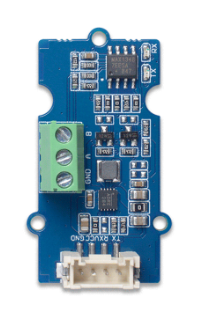
The Grove RS485 is a communication module manufactured by Seeed, designed to facilitate long-distance serial communication using the RS485 standard. RS485 is a robust communication protocol widely used in industrial environments due to its ability to transmit data reliably over long distances and in noisy conditions. The Grove RS485 module is compatible with the Grove ecosystem, making it easy to integrate into various projects.
Explore Projects Built with Grove rs485

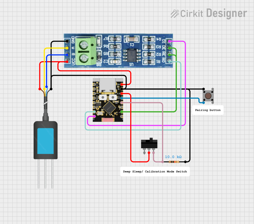

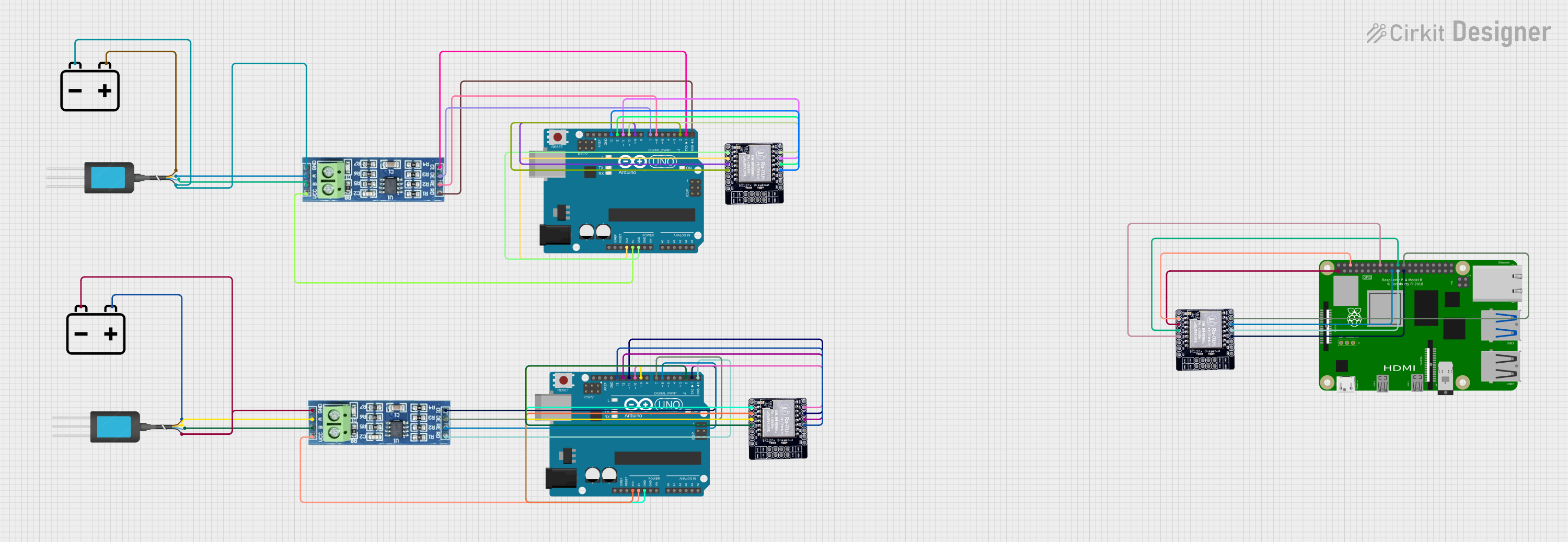
Explore Projects Built with Grove rs485
Common Applications and Use Cases
- Industrial automation and control systems
- Building management systems (e.g., HVAC, lighting control)
- Data acquisition systems
- Long-distance sensor networks
- Communication between multiple microcontrollers or devices on the same bus
Technical Specifications
The Grove RS485 module is built to provide reliable and efficient communication. Below are its key technical details:
Key Technical Details
| Parameter | Specification |
|---|---|
| Communication Standard | RS485 |
| Operating Voltage | 3.3V / 5V |
| Baud Rate | Up to 115200 bps |
| Communication Distance | Up to 1200 meters (depending on cable quality) |
| Connector Type | Grove 4-pin interface |
| Operating Temperature | -40°C to 85°C |
| Dimensions | 40mm x 20mm |
Pin Configuration and Descriptions
The Grove RS485 module uses a 4-pin Grove connector for easy interfacing. The pinout is as follows:
| Pin Number | Pin Name | Description |
|---|---|---|
| 1 | VCC | Power supply (3.3V or 5V) |
| 2 | GND | Ground |
| 3 | RX | Receive data (connected to MCU TX pin) |
| 4 | TX | Transmit data (connected to MCU RX pin) |
Usage Instructions
The Grove RS485 module is straightforward to use and can be connected to microcontrollers like Arduino UNO. Below are the steps to integrate and use the module in a circuit:
Connecting the Grove RS485 to an Arduino UNO
Hardware Setup:
- Connect the Grove RS485 module to the Grove Base Shield using a Grove cable.
- Attach the Grove Base Shield to the Arduino UNO.
- Ensure the VCC pin of the module matches the voltage level of the Arduino (5V or 3.3V).
Wiring for RS485 Communication:
- Connect the A and B terminals of the RS485 module to the corresponding A and B lines of the RS485 bus.
- Use a termination resistor (typically 120 ohms) at both ends of the RS485 bus for reliable communication over long distances.
Software Setup:
- Install the required Arduino libraries for RS485 communication (e.g.,
SoftwareSerialorRS485library). - Use the following example code to send and receive data:
- Install the required Arduino libraries for RS485 communication (e.g.,
#include <SoftwareSerial.h>

// Define RX and TX pins for SoftwareSerial
#define RX_PIN 2
#define TX_PIN 3

// Create a SoftwareSerial object
SoftwareSerial RS485Serial(RX_PIN, TX_PIN);

void setup() {
  // Initialize serial communication for debugging
  Serial.begin(9600);
  // Initialize RS485 communication
  RS485Serial.begin(9600);
  Serial.println("RS485 Communication Initialized");
}

void loop() {
  // Send data over RS485
  RS485Serial.println("Hello, RS485!");
  Serial.println("Data sent: Hello, RS485!");

  // Wait for a response
  if (RS485Serial.available()) {
    String receivedData = RS485Serial.readString();
    Serial.print("Data received: ");
    Serial.println(receivedData);
  }

  delay(1000); // Wait 1 second before sending again
}
Important Considerations and Best Practices
- Termination Resistors: Always use termination resistors at both ends of the RS485 bus to prevent signal reflections and ensure reliable communication.
- Cable Quality: Use twisted-pair cables for long-distance communication to minimize noise and signal degradation.
- Baud Rate Matching: Ensure all devices on the RS485 bus are configured to use the same baud rate.
- Grounding: Properly ground all devices on the RS485 bus to avoid ground loops and communication errors.
Troubleshooting and FAQs
Common Issues and Solutions
No Communication Between Devices:
- Verify the wiring of the A and B lines. Reversing these lines will prevent communication.
- Check that all devices on the RS485 bus are using the same baud rate.
Data Corruption or Noise:
- Ensure proper termination resistors (120 ohms) are installed at both ends of the RS485 bus.
- Use shielded or twisted-pair cables to reduce noise interference.
Module Not Powering On:
- Confirm that the VCC pin is connected to the correct voltage (3.3V or 5V).
- Check the Grove cable and connections for any loose or damaged wires.
Intermittent Communication Failures:
- Verify that the total cable length does not exceed the RS485 standard limit (1200 meters).
- Ensure all devices share a common ground.
FAQs
Q: Can I connect multiple Grove RS485 modules to the same bus?
A: Yes, RS485 supports multi-device communication. You can connect up to 32 devices on the same bus.
Q: What is the maximum baud rate supported by the Grove RS485 module?
A: The module supports baud rates up to 115200 bps.
Q: Do I need additional components to use the Grove RS485 module?
A: You may need termination resistors (120 ohms) for long-distance communication and a Grove Base Shield for easy connection to an Arduino.
Q: Can the Grove RS485 module be used with 3.3V microcontrollers?
A: Yes, the module supports both 3.3V and 5V operating voltages, making it compatible with a wide range of microcontrollers.
By following this documentation, you can effectively integrate and use the Grove RS485 module in your projects.