
How to Use Konektor out4: Examples, Pinouts, and Specs
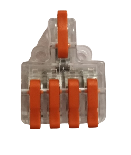
 Design with Konektor out4 in Cirkit Designer
Introduction
The Konektor out4 is a versatile connector designed for output connections in electronic circuits. It facilitates the reliable transfer of signals or power from one component to another, ensuring stable and efficient operation. This component is widely used in various applications, including power distribution, signal routing, and interfacing between modules in embedded systems.
Explore Projects Built with Konektor out4
 Open Project in Cirkit Designer
 Open Project in Cirkit Designer
 Open Project in Cirkit Designer
 Open Project in Cirkit Designer
Explore Projects Built with Konektor out4
Open Project in Cirkit DesignerOpen Project in Cirkit DesignerOpen Project in Cirkit DesignerOpen Project in Cirkit DesignerCommon Applications and Use Cases
- Power output connections in electronic devices
- Signal transmission in embedded systems
- Interfacing between sensors, actuators, and controllers
- Modular circuit designs requiring detachable connections
Technical Specifications
Key Technical Details
| Parameter | Value |
|---|---|
| Connector Type | 4-pin output connector |
| Rated Voltage | 30V DC |
| Rated Current | 3A |
| Contact Resistance | ≤ 20 mΩ |
| Insulation Resistance | ≥ 1000 MΩ |
| Operating Temperature | -40°C to +85°C |
| Material | High-grade thermoplastic |
| Mounting Type | Through-hole or panel mount |
Pin Configuration and Descriptions
The Konektor out4 features a 4-pin configuration, with each pin serving a specific purpose. Below is the pinout description:
| Pin Number | Function | Description |
|---|---|---|
| 1 | V+ (Power) | Positive voltage output |
| 2 | GND (Ground) | Ground connection |
| 3 | Signal Out | Signal output for data or control signals |
| 4 | NC (No Connect) | Reserved for future use or left unconnected |
Usage Instructions
How to Use the Konektor out4 in a Circuit
Mounting the Connector:
- For through-hole mounting, solder the pins securely onto the PCB.
- For panel mounting, use the provided screws or clips to attach the connector to the panel.
Wiring the Pins:
- Connect the V+ pin to the positive voltage source.
- Connect the GND pin to the ground of the circuit.
- Use the Signal Out pin to transmit data or control signals to the receiving component.
- Leave the NC pin unconnected unless specified otherwise in your design.
Testing the Connection:
- Verify the continuity of the connections using a multimeter.
- Ensure there are no short circuits between adjacent pins.
Important Considerations and Best Practices
- Voltage and Current Ratings: Do not exceed the rated voltage (30V DC) or current (3A) to avoid damage to the connector or connected components.
- Proper Insulation: Ensure that the connector is properly insulated to prevent accidental short circuits.
- Secure Connections: Use appropriate locking mechanisms (if available) to prevent accidental disconnection during operation.
- Environmental Conditions: Avoid exposing the connector to extreme temperatures or moisture beyond its specified operating range.
Example: Connecting to an Arduino UNO
The Konektor out4 can be used to interface an Arduino UNO with external components. Below is an example of connecting an LED to the Arduino using the connector:
Circuit Setup
- Pin 1 (V+): Connect to the Arduino's 5V pin.
- Pin 2 (GND): Connect to the Arduino's GND pin.
- Pin 3 (Signal Out): Connect to a digital output pin (e.g., D9) on the Arduino.
Arduino Code
// Example code to control an LED connected via Konektor out4
const int ledPin = 9; // Pin connected to Signal Out (Pin 3 of Konektor out4)

void setup() {
  pinMode(ledPin, OUTPUT); // Set the pin as an output
}

void loop() {
  digitalWrite(ledPin, HIGH); // Turn the LED on
  delay(1000);               // Wait for 1 second
  digitalWrite(ledPin, LOW);  // Turn the LED off
  delay(1000);               // Wait for 1 second
}
Troubleshooting and FAQs
Common Issues and Solutions
No Signal or Power Output:
- Cause: Loose or improper connections.
Solution: Check all connections and ensure the pins are securely soldered or fastened. - Cause: Exceeding voltage or current ratings.
Solution: Verify that the input voltage and current are within the specified limits.
- Cause: Loose or improper connections.
Intermittent Connections:
- Cause: Poor contact between the connector and mating component.
Solution: Clean the connector pins and ensure proper alignment during connection.
- Cause: Poor contact between the connector and mating component.
Overheating:
- Cause: Excessive current flow.
Solution: Reduce the load current to within the rated 3A limit.
- Cause: Excessive current flow.
FAQs
Q1: Can the Konektor out4 be used for AC signals?
A1: Yes, the connector can handle low-voltage AC signals, provided the voltage and current do not exceed the specified ratings.
Q2: Is the connector waterproof?
A2: No, the Konektor out4 is not waterproof. Use additional sealing or enclosures for outdoor or moisture-prone environments.
Q3: Can I use all four pins for custom purposes?
A3: The NC (No Connect) pin is reserved and should not be used unless specified in your design. The other three pins can be used as described in the pinout table.
By following this documentation, you can effectively integrate the Konektor out4 into your electronic projects for reliable output connections.