How to Use traffic light module: Examples, Pinouts, and Specs
Introduction
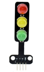
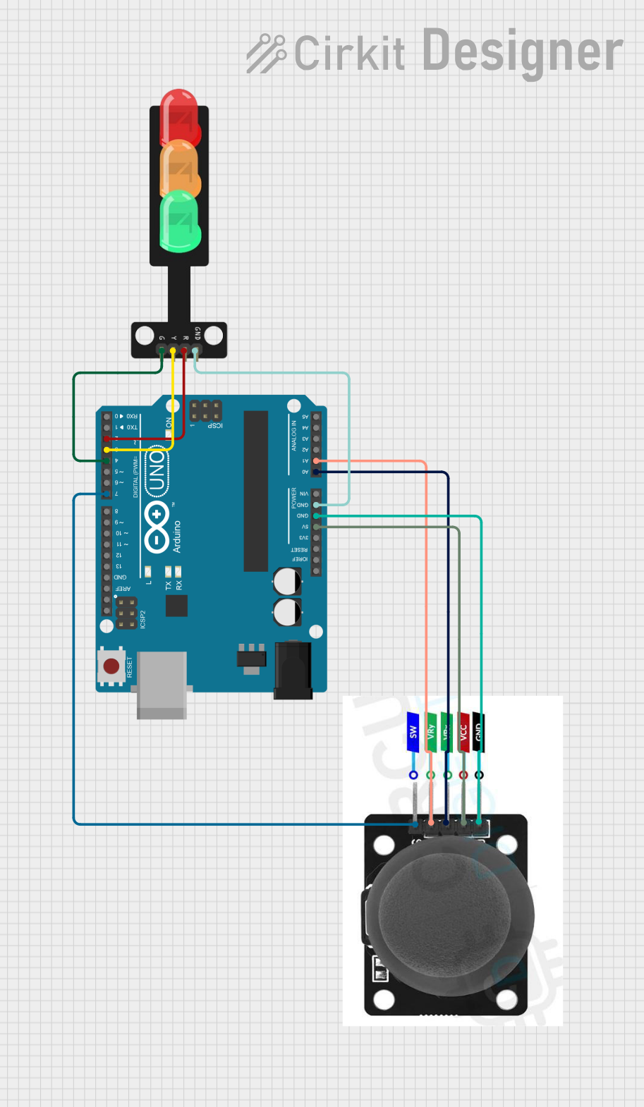
The traffic light module is an electronic component designed to simulate the operation of a real-world traffic signal. It typically features three LEDs: red, yellow, and green, which represent stop, caution, and go signals, respectively. This module is widely used in educational projects, prototyping, and model simulations to demonstrate traffic control systems or to teach basic programming and electronics concepts.
Explore Projects Built with traffic light module
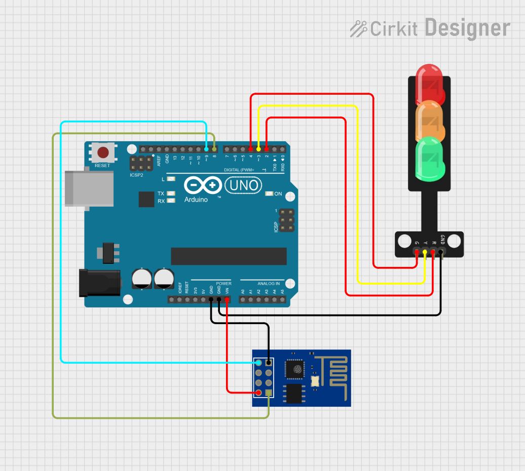
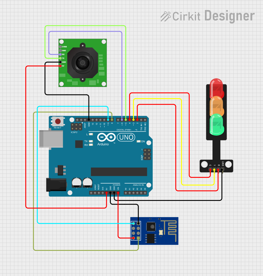
Explore Projects Built with traffic light module
Common Applications and Use Cases
- Traffic signal simulations in model cities or prototypes
- Educational projects for learning programming and electronics
- Demonstrating state machines and timing control in embedded systems
- Arduino-based projects for beginners and hobbyists
- Smart traffic management system prototypes
Technical Specifications
Below are the key technical details of a typical traffic light module:
| Parameter | Value |
|---|---|
| Operating Voltage | 3.3V - 5V |
| Current Consumption | ~20mA per LED |
| LED Colors | Red, Yellow, Green |
| Dimensions | ~30mm x 20mm x 10mm |
| Interface Type | Digital pins |
| Mounting Type | PCB-mounted or breadboard-compatible |
Pin Configuration and Descriptions
The traffic light module typically has three or more pins for connection. Below is a table describing the pin configuration:
| Pin | Name | Description |
|---|---|---|
| 1 | GND | Ground pin. Connect to the ground of the power supply or microcontroller. |
| 2 | VCC | Power supply pin. Connect to 3.3V or 5V, depending on the module specifications. |
| 3 | Red LED Signal | Digital input to control the red LED. Set HIGH to turn on the red LED. |
| 4 | Yellow LED Signal | Digital input to control the yellow LED. Set HIGH to turn on the yellow LED. |
| 5 | Green LED Signal | Digital input to control the green LED. Set HIGH to turn on the green LED. |
Usage Instructions
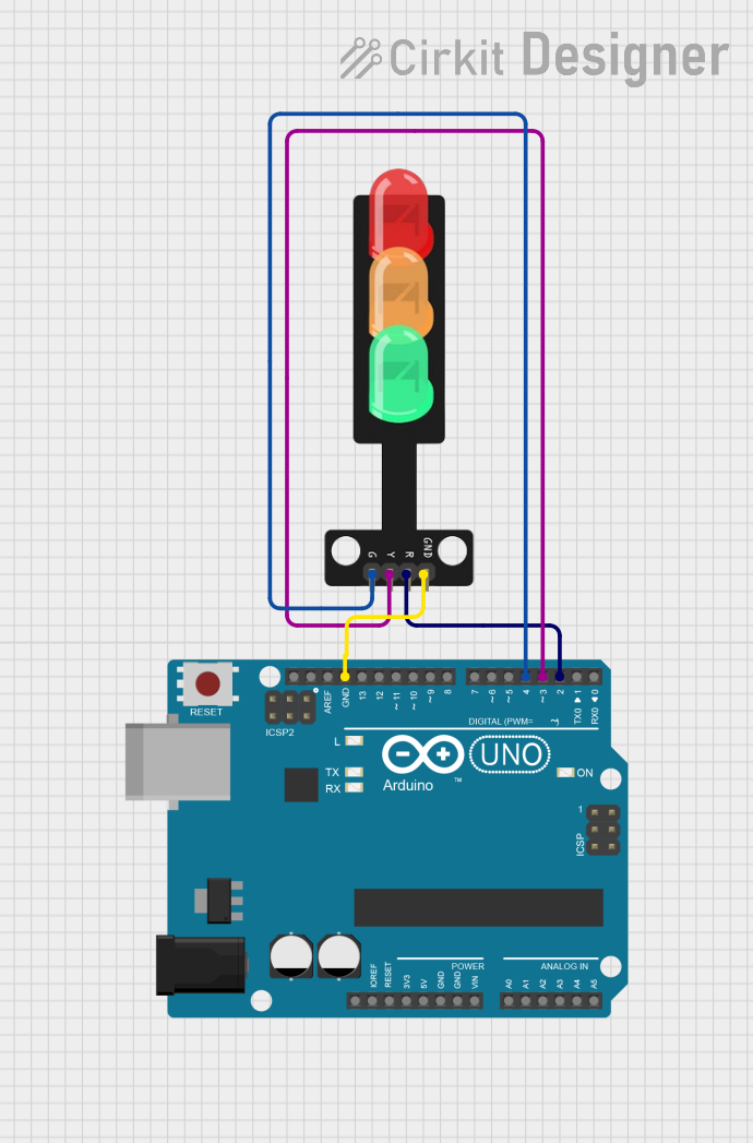
How to Use the Traffic Light Module in a Circuit
- Power the Module: Connect the
VCCpin to a 3.3V or 5V power source and theGNDpin to the ground. - Control the LEDs: Use digital output pins from a microcontroller (e.g., Arduino UNO) to control the red, yellow, and green LEDs. Each LED is controlled by its respective signal pin.
- Resistors: If the module does not have built-in resistors, add appropriate current-limiting resistors (e.g., 220Ω) in series with each LED signal pin to prevent damage to the LEDs.
Important Considerations and Best Practices
- Voltage Compatibility: Ensure the module's operating voltage matches your microcontroller's output voltage (3.3V or 5V).
- Current Limiting: Verify whether the module includes built-in resistors. If not, add external resistors to limit current through the LEDs.
- Timing Control: Use software delays or timers to simulate realistic traffic light timing (e.g., red for 10 seconds, yellow for 2 seconds, green for 8 seconds).
- Avoid Overdriving LEDs: Do not exceed the recommended current for the LEDs to prevent overheating or damage.
Example Code for Arduino UNO
Below is an example Arduino sketch to control the traffic light module:
// Pin definitions for the traffic light module
const int redPin = 8;    // Connect the red LED signal pin to digital pin 8
const int yellowPin = 9; // Connect the yellow LED signal pin to digital pin 9
const int greenPin = 10; // Connect the green LED signal pin to digital pin 10

void setup() {
  // Set the LED pins as outputs
  pinMode(redPin, OUTPUT);
  pinMode(yellowPin, OUTPUT);
  pinMode(greenPin, OUTPUT);
}

void loop() {
  // Turn on the red LED and wait for 10 seconds
  digitalWrite(redPin, HIGH);
  digitalWrite(yellowPin, LOW);
  digitalWrite(greenPin, LOW);
  delay(10000); // 10 seconds

  // Turn on the yellow LED and wait for 2 seconds
  digitalWrite(redPin, LOW);
  digitalWrite(yellowPin, HIGH);
  digitalWrite(greenPin, LOW);
  delay(2000); // 2 seconds

  // Turn on the green LED and wait for 8 seconds
  digitalWrite(redPin, LOW);
  digitalWrite(yellowPin, LOW);
  digitalWrite(greenPin, HIGH);
  delay(8000); // 8 seconds
}
Troubleshooting and FAQs
Common Issues and Solutions
LEDs Not Lighting Up
- Cause: Incorrect wiring or loose connections.
- Solution: Double-check the connections between the module and the microcontroller. Ensure the
VCCandGNDpins are properly connected.
LEDs Too Dim
- Cause: Insufficient voltage or missing current-limiting resistors.
- Solution: Verify the power supply voltage and ensure resistors are correctly sized and connected.
Module Overheating
- Cause: Excessive current through the LEDs.
- Solution: Use appropriate resistors to limit the current to each LED.
Incorrect LED Behavior
- Cause: Software logic errors or incorrect pin assignments.
- Solution: Check the Arduino code for errors and ensure the pin numbers match the module's connections.
FAQs
Q: Can I use the traffic light module with a Raspberry Pi?
A: Yes, the module can be used with a Raspberry Pi. However, since the Raspberry Pi operates at 3.3V logic, ensure the module is compatible or use a level shifter if necessary.
Q: Do I need external resistors for this module?
A: Some modules include built-in resistors, while others do not. Check the module's datasheet or test with a multimeter to confirm. If resistors are not included, add external resistors (e.g., 220Ω) in series with each LED.
Q: Can I adjust the timing for the LEDs?
A: Yes, you can modify the delay() values in the Arduino code to adjust the timing for each LED.
Q: What happens if I connect the module to a higher voltage (e.g., 12V)?
A: Connecting the module to a voltage higher than its rated operating voltage (typically 5V) can damage the LEDs or other components. Always use the recommended voltage range.