How to Use SparkFun SAMD21 Dev Breakout: Examples, Pinouts, and Specs
Introduction
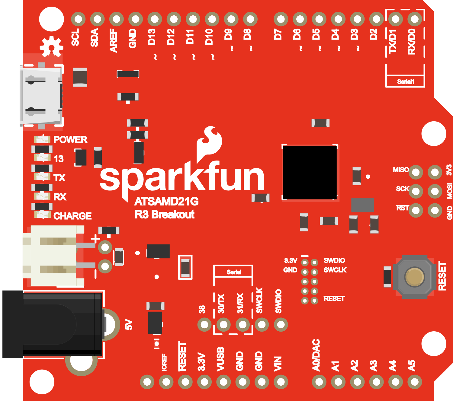
The SparkFun SAMD21 Dev Breakout is a versatile development board that harnesses the power of the Microchip ATSAMD21G18, an ARM Cortex-M0+ microcontroller. This board is an excellent choice for makers and hobbyists looking to step up from platforms like the Arduino Uno, as it provides a significant boost in performance and memory while maintaining a familiar programming environment through the Arduino IDE. Common applications include IoT devices, wearables, and complex control systems.
Explore Projects Built with SparkFun SAMD21 Dev Breakout

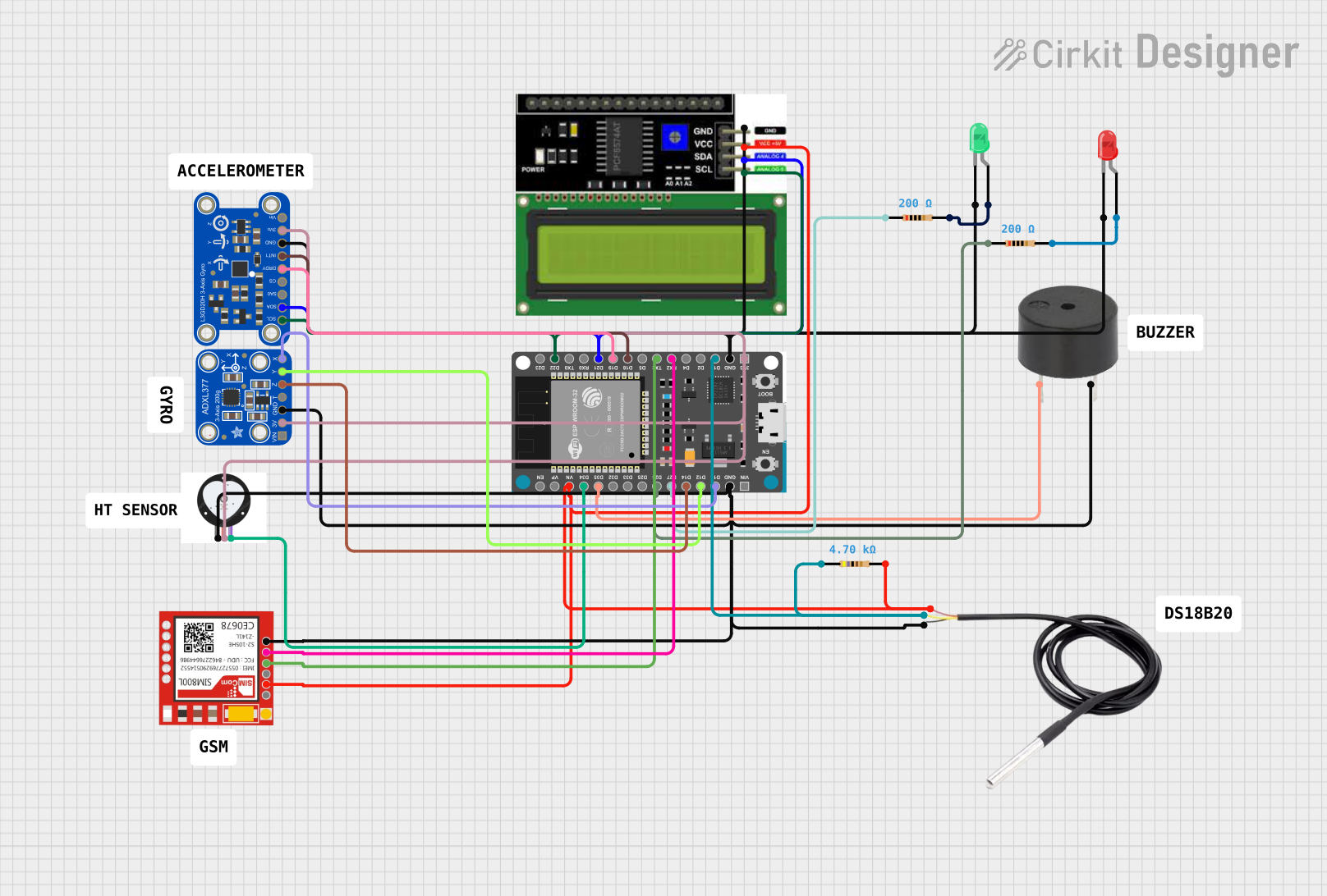
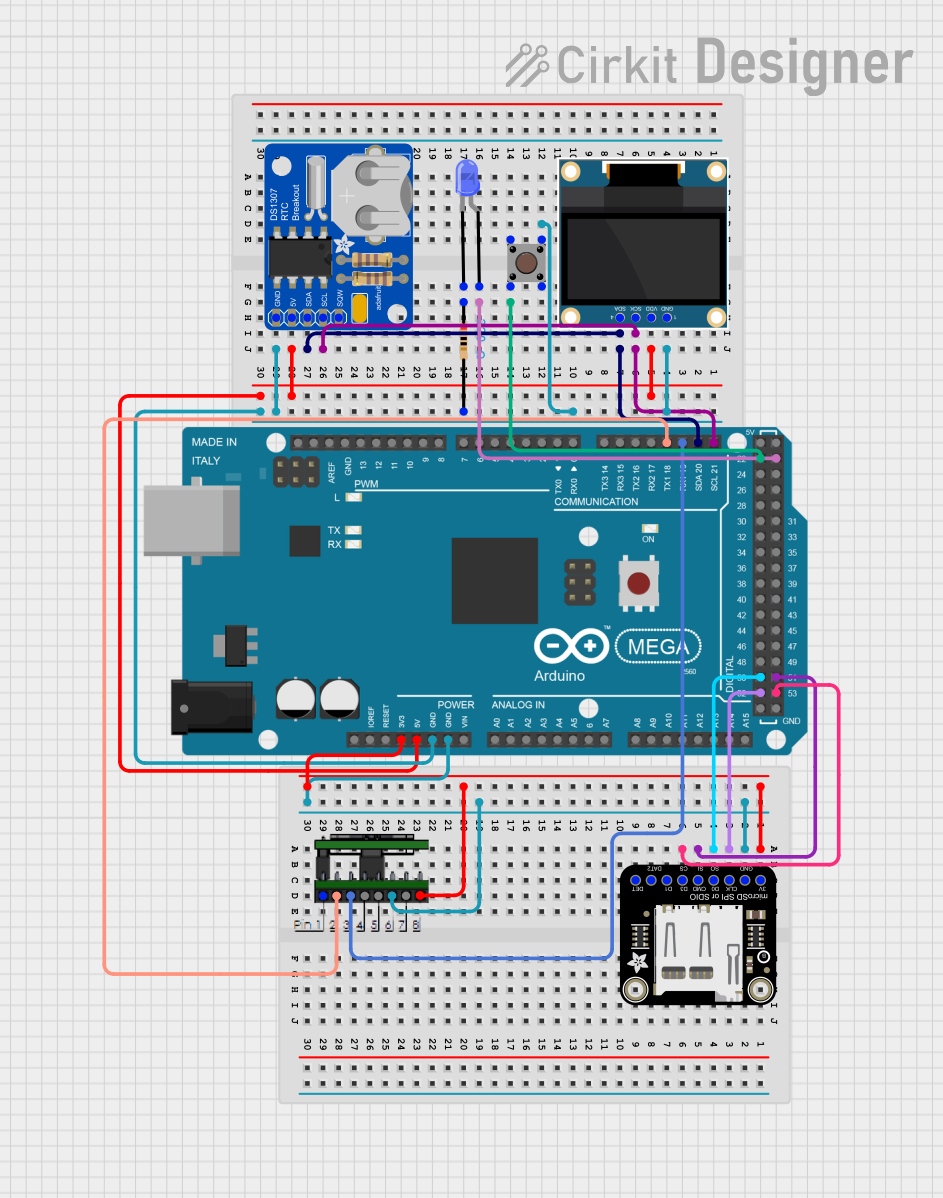
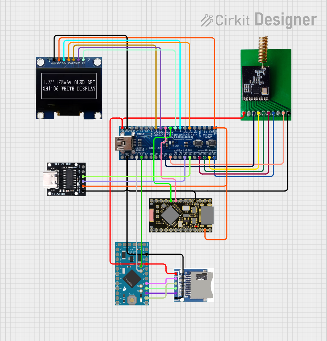
Explore Projects Built with SparkFun SAMD21 Dev Breakout
Technical Specifications
Key Features
- Microcontroller: ATSAMD21G18, 32-bit ARM Cortex-M0+
- Operating Voltage: 3.3V
- Input Voltage: 5V (via USB) or 7-15V (via VIN)
- Digital I/O Pins: 20
- Analog Input Pins: 6
- PWM Output: 10
- UARTs: 1
- SPI Interfaces: 1
- I2C Interfaces: 1
- Flash Memory: 256KB
- SRAM: 32KB
- Clock Speed: 48MHz
Pin Configuration
| Pin Number | Function | Description |
|---|---|---|
| 1 | VIN | Input voltage to the board |
| 2 | GND | Ground |
| 3-8 | Digital Pins | Digital input/output, PWM capable |
| 9 | RESET | Reset pin, active low |
| 10-15 | Analog Pins | Analog input |
| 16-17 | I2C (SDA, SCL) | I2C data and clock lines |
| 18-19 | SPI (MISO, MOSI, SCK) | SPI communication lines |
| 20 | UART (RX, TX) | UART communication lines |
Usage Instructions
Setting Up the Development Environment
- Install the Arduino IDE from the official Arduino website.
- Open the Arduino IDE, go to
File > Preferences, and add the following URL to the "Additional Boards Manager URLs" field:https://adafruit.github.io/arduino-board-index/package_adafruit_index.json - Go to
Tools > Board > Boards Manager, search for "SAMD", and install the "Arduino SAMD Boards" package. - Select the SparkFun SAMD21 Dev Breakout from
Tools > Board.
Connecting to a Circuit
- Ensure that the board is powered correctly through the USB or VIN pin.
- Connect digital and analog pins as required for your application, respecting the voltage and current limitations.
- Use the RESET pin to reset the microcontroller if necessary.
Programming the Board
- Connect the board to your computer using a micro USB cable.
- Select the correct port from
Tools > Port. - Write your sketch and upload it to the board using the
Uploadbutton.
Best Practices
- Always disconnect the board from power sources before making or altering connections.
- Use a current limiting resistor with LEDs and other sensitive components.
- Avoid exposing the board to static discharge, moisture, or extreme temperatures.
Troubleshooting and FAQs
Common Issues
- Board not recognized: Ensure that the correct drivers are installed and the USB cable is functioning.
- Sketch not uploading: Check the selected board and port in the Arduino IDE. Press the reset button twice quickly to enter bootloader mode if necessary.
- Unexpected behavior: Verify that the power supply is adequate and the pins are configured correctly in the sketch.
FAQs
Can I power the board with a battery? Yes, you can power the board with a battery connected to the VIN pin, within the 7-15V range.
What is the maximum current per I/O pin? The maximum DC current per I/O pin is 7 mA.
How do I use the onboard LED? The onboard LED is connected to pin 13. You can control it using digital write functions in your sketch.
Example Code for Arduino UNO
Here's a simple example of blinking the onboard LED:
// Pin 13 has an LED connected on most Arduino boards.
int led = 13;

// the setup routine runs once when you press reset:
void setup() {
  // initialize the digital pin as an output.
  pinMode(led, OUTPUT);
}

// the loop routine runs over and over again forever:
void loop() {
  digitalWrite(led, HIGH);   // turn the LED on (HIGH is the voltage level)
  delay(1000);               // wait for a second
  digitalWrite(led, LOW);    // turn the LED off by making the voltage LOW
  delay(1000);               // wait for a second
}
Remember to adjust the pin number and settings according to the SparkFun SAMD21 Dev Breakout specifications when adapting code for this board.