How to Use RHINO Power Supply: Examples, Pinouts, and Specs
Introduction
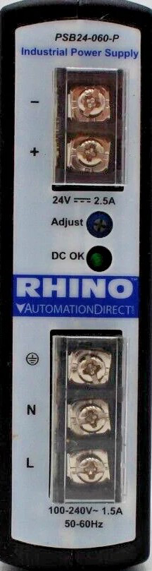
The RHINO Power Supply (Model: PSB24-060-P) is a reliable and robust power supply designed for a wide range of electronic applications. Manufactured by RHINO, this power supply provides stable voltage and current, ensuring consistent performance for powering circuits and devices. Its durable design and high efficiency make it suitable for industrial, commercial, and hobbyist projects.
Explore Projects Built with RHINO Power Supply
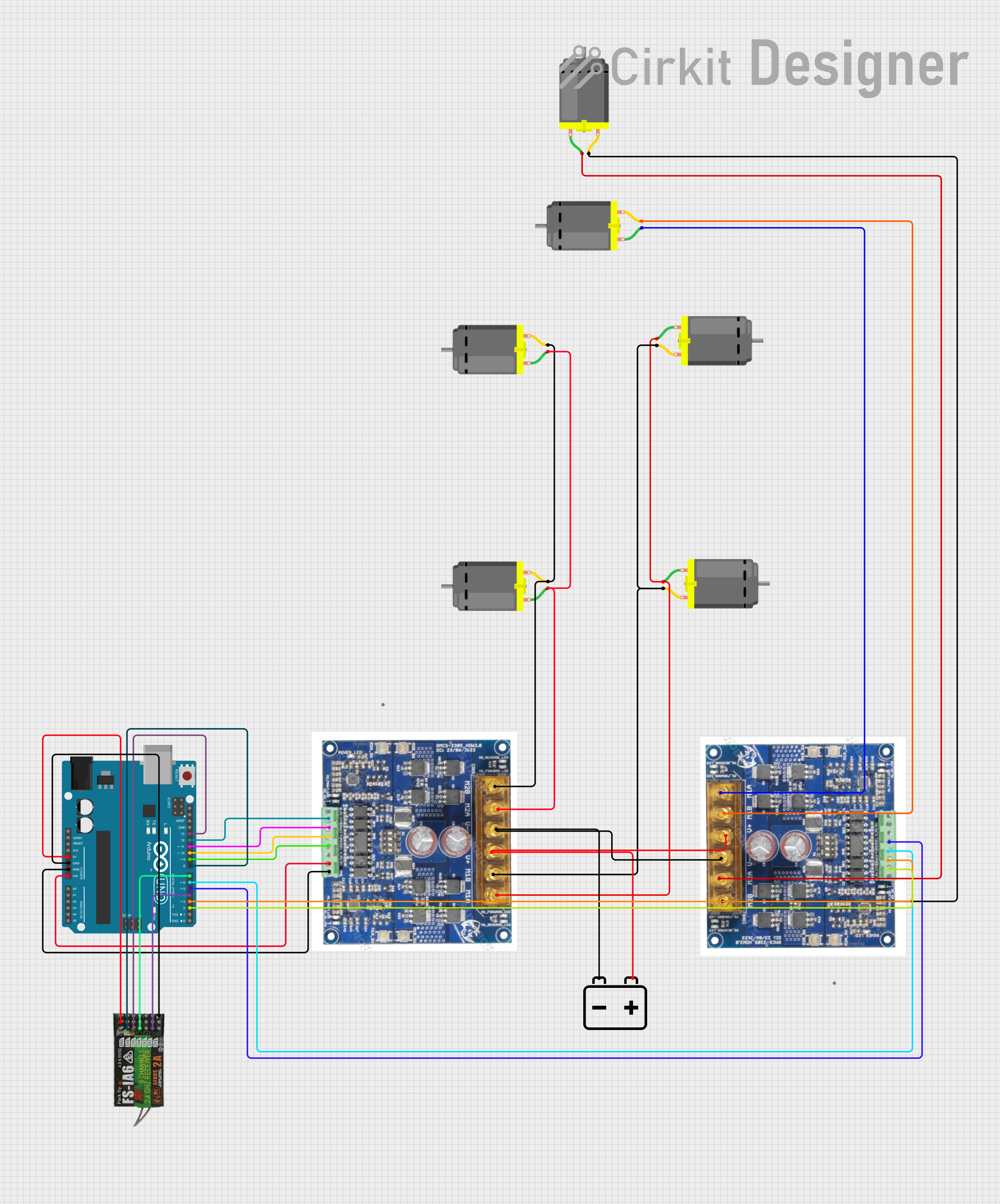
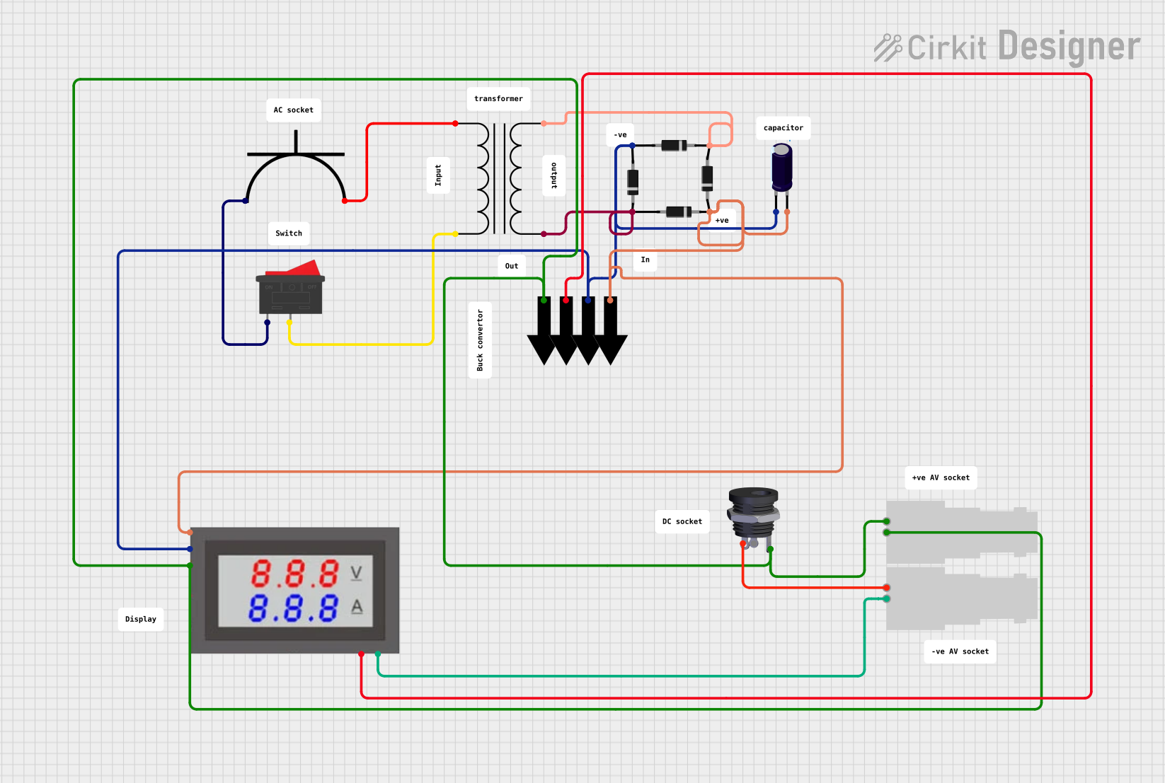


Explore Projects Built with RHINO Power Supply
Common Applications and Use Cases
- Powering industrial control systems and automation equipment
- Supplying stable voltage to microcontrollers, sensors, and actuators
- Use in laboratory setups for testing and prototyping
- Powering LED lighting systems and other low-voltage devices
- Applications requiring reliable DC power in harsh environments
Technical Specifications
The following table outlines the key technical specifications of the RHINO PSB24-060-P power supply:
| Parameter | Specification |
|---|---|
| Input Voltage Range | 85–264 VAC (47–63 Hz) / 120–370 VDC |
| Output Voltage | 24 VDC |
| Output Current | 2.5 A |
| Output Power | 60 W |
| Efficiency | ≥ 88% |
| Operating Temperature | -25°C to +70°C |
| Storage Temperature | -40°C to +85°C |
| Protection Features | Overload, Overvoltage, Short Circuit |
| Dimensions | 125 mm x 97 mm x 38 mm |
| Weight | 0.4 kg |
| Mounting Type | DIN Rail |
| Certifications | CE, UL508, RoHS |
Pin Configuration and Descriptions
The RHINO PSB24-060-P power supply has the following terminal connections:
| Pin/Terminal | Label | Description |
|---|---|---|
| 1 | L | AC Line Input |
| 2 | N | AC Neutral Input |
| 3 | +V | Positive DC Output |
| 4 | -V | Negative DC Output |
| 5 | FG | Frame Ground (Earth) |
Usage Instructions
How to Use the Component in a Circuit
Mounting the Power Supply:
Secure the RHINO PSB24-060-P to a DIN rail in your enclosure or control panel. Ensure proper ventilation around the unit to prevent overheating.Connecting the Input:
- Connect the AC line (L) and neutral (N) terminals to the appropriate mains power source.
- Ensure the input voltage is within the specified range (85–264 VAC).
- Optionally, connect the frame ground (FG) terminal to the earth ground for safety.
Connecting the Output:
- Connect the +V and -V terminals to the load or circuit requiring 24 VDC.
- Verify that the total current draw of the connected devices does not exceed 2.5 A.
Powering On:
- After all connections are secure, turn on the mains power.
- The power supply will provide a stable 24 VDC output to the connected devices.
Important Considerations and Best Practices
- Load Requirements: Ensure the total load does not exceed the rated output power (60 W). Overloading may trigger the protection features or damage the unit.
- Ventilation: Maintain adequate airflow around the power supply to prevent overheating, especially in high-temperature environments.
- Wiring: Use appropriately rated wires for both input and output connections to handle the current safely.
- Safety: Always disconnect the power supply from the mains before making any wiring changes.
Example: Connecting to an Arduino UNO
The RHINO PSB24-060-P can be used to power an Arduino UNO via its VIN pin. Below is an example wiring setup and Arduino code:
Wiring:
- Connect the +V terminal of the power supply to the VIN pin of the Arduino UNO.
- Connect the -V terminal of the power supply to the GND pin of the Arduino UNO.
Arduino Code:
// Example code to blink an LED connected to pin 13 of the Arduino UNO
// Ensure the RHINO power supply is providing 24V to the Arduino's VIN pin

void setup() {
  pinMode(13, OUTPUT); // Set pin 13 as an output
}

void loop() {
  digitalWrite(13, HIGH); // Turn the LED on
  delay(1000);            // Wait for 1 second
  digitalWrite(13, LOW);  // Turn the LED off
  delay(1000);            // Wait for 1 second
}
Troubleshooting and FAQs
Common Issues and Solutions
| Issue | Possible Cause | Solution |
|---|---|---|
| No output voltage | Input power not connected or incorrect | Verify AC input connections and voltage range |
| Output voltage fluctuates | Overload or unstable input voltage | Reduce load or stabilize input power |
| Power supply overheats | Insufficient ventilation or high ambient temp | Improve airflow or reduce ambient temperature |
| Protection features triggered | Short circuit or overvoltage on output | Check and resolve output wiring issues |
FAQs
Can I use this power supply with a 12 V device?
No, the RHINO PSB24-060-P provides a fixed 24 VDC output. Using it with a 12 V device may damage the device. Consider using a step-down converter if needed.What happens if the load exceeds 2.5 A?
The power supply's overload protection will activate, shutting down the output to prevent damage. Reduce the load and restart the power supply.Is the power supply suitable for outdoor use?
The RHINO PSB24-060-P is not weatherproof. Use it in a protected, indoor environment or within a weatherproof enclosure.Can I use this power supply with a battery backup system?
Yes, the power supply can be integrated into a battery backup system, provided the system is designed to handle 24 VDC input.
By following this documentation, users can effectively utilize the RHINO PSB24-060-P power supply in their projects and troubleshoot common issues with ease.