
How to Use icl7660: Examples, Pinouts, and Specs
 Design with icl7660 in Cirkit Designer
Introduction
The ICL7660 is a versatile voltage converter integrated circuit (IC) designed to generate a negative voltage from a positive voltage supply. It operates using a charge-pump principle, making it an efficient and compact solution for applications requiring a dual power supply. The ICL7660 is widely used in analog circuits, such as operational amplifiers, data acquisition systems, and instrumentation, where a negative voltage rail is essential.
Explore Projects Built with icl7660
 Open Project in Cirkit Designer
 Open Project in Cirkit Designer
 Open Project in Cirkit Designer
 Open Project in Cirkit Designer
Explore Projects Built with icl7660
Open Project in Cirkit DesignerOpen Project in Cirkit DesignerOpen Project in Cirkit DesignerOpen Project in Cirkit DesignerCommon Applications:
- Powering operational amplifiers in dual-supply configurations
- Generating negative voltage rails for analog circuits
- Battery-powered systems requiring compact voltage conversion
- Portable instrumentation and data acquisition systems
Technical Specifications
Key Technical Details:
- Input Voltage Range: +1.5V to +10V
- Output Voltage: Approximately -Vin (negative of the input voltage)
- Maximum Output Current: 20mA (typical), 40mA (maximum, with reduced efficiency)
- Quiescent Current: 200µA (typical)
- Efficiency: Up to 98% (depending on load conditions)
- Operating Temperature Range: 0°C to +70°C (commercial grade)
- Package Types: DIP-8, SOIC-8
Pin Configuration and Descriptions:
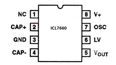
The ICL7660 is an 8-pin IC. Below is the pinout and description:
| Pin Number | Pin Name | Description |
|---|---|---|
| 1 | V+ | Positive power supply input (1.5V to 10V). |
| 2 | CAP+ | Positive terminal for the external charge-pump capacitor. |
| 3 | GND | Ground (0V reference). |
| 4 | CAP- | Negative terminal for the external charge-pump capacitor. |
| 5 | VOUT | Negative voltage output (-Vin). |
| 6 | LV | Low-voltage pin (connect to GND for input voltage below 3.5V). |
| 7 | OSC | Oscillator control pin (leave open for default frequency, or connect to GND |
| 8 | V+ | Positive power supply input (same as Pin 1). |
Usage Instructions
How to Use the ICL7660 in a Circuit:
- Power Supply: Connect the positive voltage supply (1.5V to 10V) to the V+ pin (Pin 1 and Pin 8). Connect the GND pin (Pin 3) to the ground of the circuit.
- Charge-Pump Capacitors:
- Connect a 10µF capacitor between CAP+ (Pin 2) and CAP- (Pin 4).
- Connect another 10µF capacitor between VOUT (Pin 5) and GND (Pin 3).
- Ensure the capacitors are rated for at least twice the input voltage for reliability.
- Low Voltage Operation: If the input voltage is below 3.5V, connect the LV pin (Pin 6) to GND to optimize performance.
- Oscillator Control: Leave the OSC pin (Pin 7) unconnected for the default operating frequency (10kHz). For custom frequency control, refer to the datasheet.
Important Considerations:
- Capacitor Selection: Use low-ESR capacitors (e.g., ceramic or tantalum) for optimal performance.
- Load Current: Avoid exceeding the maximum output current (40mA) to prevent voltage drop and inefficiency.
- Bypass Capacitor: Place a 0.1µF ceramic capacitor close to the V+ pin to reduce noise and improve stability.
- Thermal Management: Ensure adequate ventilation or heat dissipation if operating near the maximum current limit.
Example Circuit with Arduino UNO:
The ICL7660 can be used to generate a negative voltage for powering an op-amp in an Arduino-based project. Below is an example:
/* Example: Using ICL7660 to generate -5V for an op-amp in an Arduino project.
   This code demonstrates reading an analog signal and outputting a processed
   signal using an op-amp powered by the ICL7660. */

// Define the analog input and output pins
const int analogInputPin = A0;  // Analog input pin for the signal
const int analogOutputPin = 9; // PWM output pin for processed signal

void setup() {
  pinMode(analogInputPin, INPUT);  // Set the input pin mode
  pinMode(analogOutputPin, OUTPUT); // Set the output pin mode
  Serial.begin(9600); // Initialize serial communication for debugging
}

void loop() {
  int sensorValue = analogRead(analogInputPin); // Read the analog input
  int outputValue = map(sensorValue, 0, 1023, 0, 255);
  // Map the input value to a PWM range (0-255)

  analogWrite(analogOutputPin, outputValue); // Output the processed signal
  Serial.println(outputValue); // Print the output value for debugging
  delay(10); // Small delay for stability
}
Notes:
- The ICL7660 provides the negative voltage rail (-5V) required by the op-amp in this circuit.
- Ensure proper decoupling capacitors are used for both the ICL7660 and the op-amp.
Troubleshooting and FAQs
Common Issues and Solutions:
Output Voltage is Incorrect or Unstable:
- Verify the charge-pump capacitors are correctly connected and have the proper value (10µF).
- Check for low-ESR capacitors; high ESR can cause instability.
- Ensure the input voltage is within the specified range (1.5V to 10V).
Excessive Voltage Drop Under Load:
- Ensure the load current does not exceed the maximum rating (40mA).
- Use larger capacitors (e.g., 22µF) to improve load regulation.
IC Overheating:
- Reduce the load current if it exceeds the recommended operating range.
- Check for proper ventilation or heat dissipation.
No Output Voltage:
- Verify all connections, especially the charge-pump capacitors.
- Ensure the LV pin is connected to GND if the input voltage is below 3.5V.
FAQs:
Q1: Can the ICL7660 generate a positive voltage?
A1: No, the ICL7660 is specifically designed to invert a positive voltage to a negative voltage. For positive voltage generation, consider using a boost converter IC.
Q2: What happens if I use capacitors with a lower value than 10µF?
A2: Using smaller capacitors may result in reduced efficiency, increased ripple, and unstable output voltage.
Q3: Can I use the ICL7660 with a 12V input?
A3: No, the maximum input voltage for the ICL7660 is 10V. Exceeding this limit may damage the IC.
Q4: Is the ICL7660 suitable for audio applications?
A4: Yes, but ensure proper filtering to minimize noise introduced by the charge-pump switching.
By following this documentation, users can effectively integrate the ICL7660 into their circuits and troubleshoot common issues.