Cirkit Designer Logo
Cirkit Designer
Your all-in-one circuit design IDE
Home / 
Component Documentation

How to Use 2.1mm Male: Examples, Pinouts, and Specs

Image of 2.1mm Male
Cirkit Designer LogoDesign with 2.1mm Male in Cirkit Designer

Introduction

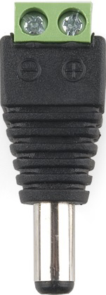
The 2.1mm Male DC Power Connector is a widely utilized component in the electronics industry, known for its reliability in establishing a secure power connection. This cylindrical-shaped connector features a 2.1mm diameter central pin surrounded by a barrel that ensures a stable electrical connection. It is commonly used to supply power to a variety of electronic devices such as routers, modems, single-board computers, and LED strip lights.

Explore Projects Built with 2.1mm Male

Use Cirkit Designer to design, explore, and prototype these projects online. Some projects support real-time simulation. Click "Open Project" to start designing instantly!
Multi-Channel Load Cell Measurement System with JYS60 Amplifiers and DAQ Integration
Image of Load Cell Circuit: A project utilizing 2.1mm Male in a practical application
This is a multi-channel load cell measurement system with several JYS60 amplifiers connected to load cells for weight or force sensing. The amplified signals are directed to a DAQ system for data capture, and power is supplied through a barrel jack. Grounding is achieved via an AdaGator Side Black component.
Cirkit Designer LogoOpen Project in Cirkit Designer
Battery-Powered Multi-Voltage Supply with Barrel Jack Connectors
Image of Battery Setup: A project utilizing 2.1mm Male in a practical application
This circuit consists of multiple 9V batteries connected in series and parallel configurations to provide power to three separate 2.1mm barrel jacks. Each barrel jack receives a different combination of series and parallel battery connections to achieve the desired voltage and current levels.
Cirkit Designer LogoOpen Project in Cirkit Designer
Arduino Nano-Based Flex Sensor Motion Tracker with Bluetooth Connectivity
Image of military designed specialzed glove: A project utilizing 2.1mm Male in a practical application
This circuit features an Arduino Nano microcontroller interfaced with multiple 2.2-inch flex resistors, an MPU6050 accelerometer/gyroscope, and an HC-05 Bluetooth module. The flex resistors are connected to the analog input pins of the Arduino, while the MPU6050 and HC-05 are connected via I2C and serial communication respectively, enabling sensor data acquisition and wireless communication.
Cirkit Designer LogoOpen Project in Cirkit Designer
Audio Signal Routing with TRRS 3.5mm Jack Breakouts
Image of 3.5mm 1W 8Ohm Speaker: A project utilizing 2.1mm Male in a practical application
This circuit is designed to interface two TRRS 3.5mm audio jacks with a standard 3.5mm audio jack, routing audio signals between them. The microcontroller present in the circuit does not have an active role as the provided code is empty.
Cirkit Designer LogoOpen Project in Cirkit Designer

Explore Projects Built with 2.1mm Male

Use Cirkit Designer to design, explore, and prototype these projects online. Some projects support real-time simulation. Click "Open Project" to start designing instantly!
Image of Load Cell Circuit: A project utilizing 2.1mm Male in a practical application
Multi-Channel Load Cell Measurement System with JYS60 Amplifiers and DAQ Integration
This is a multi-channel load cell measurement system with several JYS60 amplifiers connected to load cells for weight or force sensing. The amplified signals are directed to a DAQ system for data capture, and power is supplied through a barrel jack. Grounding is achieved via an AdaGator Side Black component.
Cirkit Designer LogoOpen Project in Cirkit Designer
Image of Battery Setup: A project utilizing 2.1mm Male in a practical application
Battery-Powered Multi-Voltage Supply with Barrel Jack Connectors
This circuit consists of multiple 9V batteries connected in series and parallel configurations to provide power to three separate 2.1mm barrel jacks. Each barrel jack receives a different combination of series and parallel battery connections to achieve the desired voltage and current levels.
Cirkit Designer LogoOpen Project in Cirkit Designer
Image of military designed specialzed glove: A project utilizing 2.1mm Male in a practical application
Arduino Nano-Based Flex Sensor Motion Tracker with Bluetooth Connectivity
This circuit features an Arduino Nano microcontroller interfaced with multiple 2.2-inch flex resistors, an MPU6050 accelerometer/gyroscope, and an HC-05 Bluetooth module. The flex resistors are connected to the analog input pins of the Arduino, while the MPU6050 and HC-05 are connected via I2C and serial communication respectively, enabling sensor data acquisition and wireless communication.
Cirkit Designer LogoOpen Project in Cirkit Designer
Image of 3.5mm 1W 8Ohm Speaker: A project utilizing 2.1mm Male in a practical application
Audio Signal Routing with TRRS 3.5mm Jack Breakouts
This circuit is designed to interface two TRRS 3.5mm audio jacks with a standard 3.5mm audio jack, routing audio signals between them. The microcontroller present in the circuit does not have an active role as the provided code is empty.
Cirkit Designer LogoOpen Project in Cirkit Designer

Common Applications and Use Cases

  • Power supply for routers and modems
  • Connection to development boards like Arduino and Raspberry Pi
  • LED lighting systems
  • CCTV camera installations
  • Portable electronics charging

Technical Specifications

Key Technical Details

  • Rated Voltage: Typically up to 24V DC
  • Rated Current: Varies, commonly up to 5A
  • Contact Resistance: Typically less than 0.05 Ohms
  • Insulation Resistance: Typically greater than 100M Ohms
  • Operating Temperature: -10°C to +70°C

Pin Configuration and Descriptions

Pin Number Description Notes
1 Center Pin (+) Positive voltage supply (V+)
2 Barrel (Outer Shell) Ground connection (GND)

Usage Instructions

How to Use the Component in a Circuit

  1. Identify Polarity: Ensure the polarity of the power supply matches the device's requirements. The center pin is typically positive, while the outer shell is negative.
  2. Voltage and Current Rating: Verify that the voltage and current ratings of the power supply do not exceed the specifications of the connector and the device.
  3. Secure Connection: Insert the 2.1mm Male DC Power Connector into the corresponding female jack until it is firmly seated.
  4. Cable Considerations: Use an appropriate gauge wire for the current being drawn to prevent overheating and voltage drop.

Important Considerations and Best Practices

  • Polarity Check: Always double-check the polarity before connecting to avoid damaging the electronic device.
  • Avoid Force: Do not apply excessive force when inserting or removing the connector to prevent damage.
  • Strain Relief: Implement strain relief mechanisms to prevent stress on the connector and cable junction.
  • Inspection: Regularly inspect the connector for signs of wear, corrosion, or damage.

Troubleshooting and FAQs

Common Issues Users Might Face

  • Loose Connections: If the device intermittently loses power, check for a loose connection at the connector.
  • Incorrect Polarity: Reversed polarity can lead to device malfunction or damage.
  • Overheating: If the connector or cable becomes hot, this may indicate an overcurrent condition or inadequate wire gauge.

Solutions and Tips for Troubleshooting

  • Tighten Connections: Ensure the connector is fully inserted and making good contact with the jack.
  • Polarity Check: Use a multimeter to verify the polarity of the power supply before connection.
  • Cable Replacement: If overheating occurs, replace the cable with one of a suitable gauge for the current load.

FAQs

Q: Can I use a 2.1mm Male DC Power Connector with a 2.5mm jack? A: No, the sizes are incompatible and attempting to do so may result in a poor connection or damage.

Q: How do I know if the connector is properly seated? A: The connector should fit snugly without wiggling and should not easily pull out from the jack.

Q: What should I do if the connector does not fit into the jack? A: Verify that both the connector and jack are indeed 2.1mm and check for any obstructions or damage.

Example Code for Arduino UNO

// Example code to demonstrate how to control a device powered by a 2.1mm Male DC Power Connector using an Arduino UNO

const int powerControlPin = 2; // Connect a relay module control pin to digital pin 2

void setup() {
  pinMode(powerControlPin, OUTPUT); // Set the power control pin as an output
}

void loop() {
  digitalWrite(powerControlPin, HIGH); // Turn on the connected device
  delay(5000); // Keep the device on for 5 seconds
  digitalWrite(powerControlPin, LOW); // Turn off the connected device
  delay(5000); // Keep the device off for 5 seconds
}

Note: The above code assumes the use of a relay module to switch the power on and off to the device connected via the 2.1mm Male DC Power Connector. Always ensure that the relay used is rated for the voltage and current of the power supply and the connected device.