
How to Use 5 wire Terminal Connector: Examples, Pinouts, and Specs
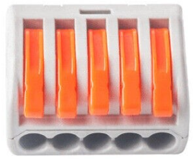
 Design with 5 wire Terminal Connector in Cirkit Designer
Introduction
The 5 Wire Terminal Connector, manufactured by WAGO, is a versatile electrical connector designed to join five separate wires securely and efficiently. This component is widely used in electrical and electronic systems to ensure reliable connections while maintaining an organized wiring setup. Its compact design and ease of use make it an essential component for both professional and DIY applications.
Explore Projects Built with 5 wire Terminal Connector
 Open Project in Cirkit Designer
 Open Project in Cirkit Designer
 Open Project in Cirkit Designer
 Open Project in Cirkit Designer
Explore Projects Built with 5 wire Terminal Connector
Open Project in Cirkit DesignerOpen Project in Cirkit DesignerOpen Project in Cirkit DesignerOpen Project in Cirkit DesignerCommon Applications and Use Cases
- Electrical wiring in industrial and residential installations
- Connecting multiple circuits in control panels
- Prototyping and testing electronic circuits
- Automotive and machinery wiring
- Renewable energy systems, such as solar panel connections
Technical Specifications
The following table outlines the key technical details of the WAGO 5 Wire Terminal Connector:
| Parameter | Specification |
|---|---|
| Manufacturer | WAGO |
| Number of Wires | 5 |
| Wire Size Compatibility | 28–12 AWG (0.08–4 mm²) |
| Voltage Rating | Up to 450V AC |
| Current Rating | Up to 32A |
| Operating Temperature | -35°C to +85°C |
| Housing Material | Polyamide (PA66), flame-retardant |
| Connection Type | Push-in spring clamp |
| Dimensions | Varies by model (e.g., 20mm x 15mm) |
| Certifications | UL, CE, RoHS compliant |
Pin Configuration and Descriptions
The 5 Wire Terminal Connector does not have traditional "pins" but instead features five wire slots for connection. Each slot is designed to accommodate a single wire, as described below:
| Slot Number | Description |
|---|---|
| 1 | Input/Output wire connection (Line 1) |
| 2 | Input/Output wire connection (Line 2) |
| 3 | Input/Output wire connection (Line 3) |
| 4 | Input/Output wire connection (Line 4) |
| 5 | Input/Output wire connection (Line 5) |
Usage Instructions
How to Use the Component in a Circuit
- Prepare the Wires: Strip approximately 8–10mm of insulation from the ends of the wires you wish to connect.
- Insert the Wires: Push each stripped wire into one of the five slots on the terminal connector. Ensure the wire is fully inserted and makes contact with the internal spring clamp.
- Verify the Connection: Gently tug on each wire to confirm it is securely held in place.
- Connect to the Circuit: Use the terminal connector to join wires from different circuits or devices as needed.
Important Considerations and Best Practices
- Wire Compatibility: Ensure the wires fall within the supported size range (28–12 AWG).
- Avoid Overloading: Do not exceed the voltage and current ratings of the connector.
- Environmental Conditions: Use the connector within the specified operating temperature range.
- Secure Mounting: If necessary, mount the connector to a stable surface to prevent movement or strain on the wires.
- Reusability: The push-in spring clamp design allows for easy removal and reinsertion of wires, making it ideal for prototyping.
Example: Connecting to an Arduino UNO
The 5 Wire Terminal Connector can be used to organize connections between an Arduino UNO and external components, such as sensors or actuators. Below is an example of how to use the connector in such a setup:
- Connect the wires from the Arduino's digital pins (e.g., D2, D3, D4) to the terminal connector.
- Use the remaining slots to connect external devices, such as LEDs or relays.
// Example Arduino code to control LEDs connected via a 5 Wire Terminal Connector

const int ledPin1 = 2; // Digital pin 2 connected to LED 1
const int ledPin2 = 3; // Digital pin 3 connected to LED 2
const int ledPin3 = 4; // Digital pin 4 connected to LED 3

void setup() {
  pinMode(ledPin1, OUTPUT); // Set pin 2 as output
  pinMode(ledPin2, OUTPUT); // Set pin 3 as output
  pinMode(ledPin3, OUTPUT); // Set pin 4 as output
}

void loop() {
  digitalWrite(ledPin1, HIGH); // Turn on LED 1
  delay(500);                 // Wait for 500ms
  digitalWrite(ledPin1, LOW);  // Turn off LED 1

  digitalWrite(ledPin2, HIGH); // Turn on LED 2
  delay(500);                 // Wait for 500ms
  digitalWrite(ledPin2, LOW);  // Turn off LED 2

  digitalWrite(ledPin3, HIGH); // Turn on LED 3
  delay(500);                 // Wait for 500ms
  digitalWrite(ledPin3, LOW);  // Turn off LED 3
}
Troubleshooting and FAQs
Common Issues Users Might Face
- Loose Connections: Wires may not be securely held if not fully inserted.
- Solution: Ensure the stripped portion of the wire is inserted completely into the slot.
- Overheating: The connector may overheat if the current exceeds the rated 32A.
- Solution: Verify the current draw of your circuit and ensure it is within the connector's limits.
- Wire Damage: Stranded wires may fray if not properly stripped or inserted.
- Solution: Use a wire stripper to cleanly remove insulation and twist stranded wires before insertion.
FAQs
Q: Can I reuse the 5 Wire Terminal Connector?
A: Yes, the push-in spring clamp design allows for easy removal and reinsertion of wires.
Q: Is the connector suitable for outdoor use?
A: The connector is not waterproof. For outdoor applications, use additional protective enclosures.
Q: Can I connect wires of different gauges?
A: Yes, as long as the wire sizes fall within the supported range (28–12 AWG).
Q: How do I know if the connection is secure?
A: After inserting the wire, gently pull on it. If it does not come loose, the connection is secure.