
How to Use PRIK-KEE-NOO 2-CH R/C + I2C: Examples, Pinouts, and Specs
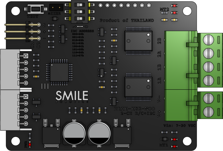
 Design with PRIK-KEE-NOO 2-CH R/C + I2C in Cirkit Designer
Introduction
The PRIK-KEE-NOO 2-CH R/C + I2C is a dual-channel remote control module with an integrated I2C interface, manufactured by Smile Robotics. This versatile module is designed for wireless communication and control in a wide range of electronic projects. It allows users to control devices remotely while also providing seamless integration with microcontrollers via the I2C protocol.
Explore Projects Built with PRIK-KEE-NOO 2-CH R/C + I2C
 Open Project in Cirkit Designer
 Open Project in Cirkit Designer
 Open Project in Cirkit Designer
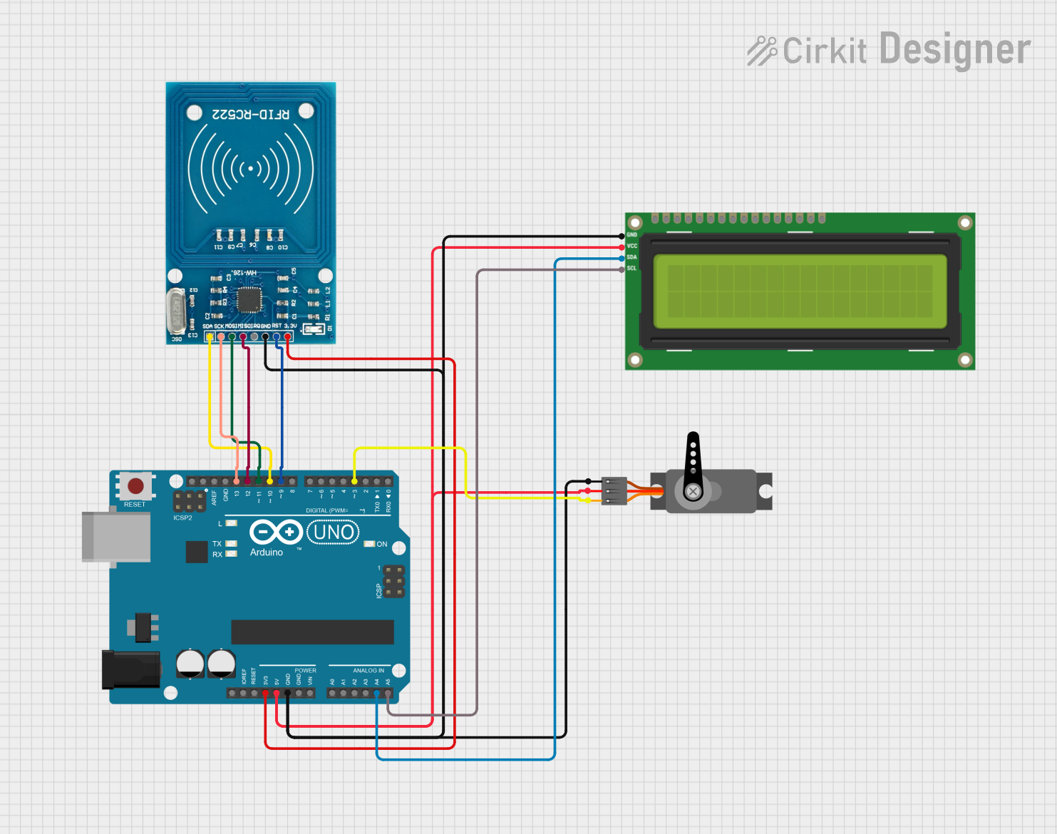 Open Project in Cirkit Designer
Explore Projects Built with PRIK-KEE-NOO 2-CH R/C + I2C
Open Project in Cirkit DesignerOpen Project in Cirkit DesignerOpen Project in Cirkit DesignerOpen Project in Cirkit DesignerCommon Applications and Use Cases
- Wireless control of robots, drones, and RC vehicles
- Home automation systems
- IoT (Internet of Things) projects requiring remote actuation
- Educational projects for learning wireless communication and I2C integration
- Prototyping remote-controlled devices
Technical Specifications
The following table outlines the key technical details of the PRIK-KEE-NOO 2-CH R/C + I2C module:
| Parameter | Specification |
|---|---|
| Operating Voltage | 3.3V to 5V |
| Communication Protocol | I2C |
| Channels | 2 (dual-channel control) |
| Frequency Range | 2.4 GHz |
| I2C Address Range | 0x10 to 0x7F (configurable) |
| Max Current Consumption | 50 mA |
| Dimensions | 30mm x 20mm x 5mm |
| Operating Temperature | -20°C to 70°C |
Pin Configuration and Descriptions
The PRIK-KEE-NOO 2-CH R/C + I2C module has the following pinout:
| Pin | Name | Description |
|---|---|---|
| 1 | VCC | Power supply input (3.3V to 5V) |
| 2 | GND | Ground connection |
| 3 | SCL | I2C clock line |
| 4 | SDA | I2C data line |
| 5 | CH1_OUT | Output for Channel 1 (PWM or digital signal for controlling devices) |
| 6 | CH2_OUT | Output for Channel 2 (PWM or digital signal for controlling devices) |
| 7 | CONFIG | Configuration pin for setting I2C address (connect to GND or VCC as needed) |
| 8 | STATUS | Status indicator pin (active HIGH when module is operational) |
Usage Instructions
How to Use the Component in a Circuit
- Power the Module: Connect the
VCCpin to a 3.3V or 5V power source and theGNDpin to ground. - I2C Connection: Connect the
SCLandSDApins to the corresponding I2C pins on your microcontroller (e.g., Arduino UNO). - Channel Outputs: Use the
CH1_OUTandCH2_OUTpins to control external devices such as motors, LEDs, or relays. - Configuration: Use the
CONFIGpin to set the I2C address if multiple modules are used in the same circuit. Refer to the manufacturer's datasheet for address configuration details. - Status Monitoring: Optionally, connect the
STATUSpin to an LED or microcontroller input to monitor the module's operational state.
Important Considerations and Best Practices
- Ensure the power supply voltage matches the module's operating range (3.3V to 5V).
- Use pull-up resistors (typically 4.7kΩ) on the
SCLandSDAlines if your microcontroller does not have internal pull-ups enabled. - Avoid placing the module near sources of electromagnetic interference (EMI) to maintain reliable wireless communication.
- For optimal performance, ensure the antenna (if external) is unobstructed and positioned away from metal surfaces.
Example Code for Arduino UNO
Below is an example Arduino sketch to control the PRIK-KEE-NOO 2-CH R/C + I2C module via I2C:
#include <Wire.h> // Include the Wire library for I2C communication

#define MODULE_I2C_ADDRESS 0x10 // Default I2C address of the module

void setup() {
  Wire.begin(); // Initialize I2C communication
  Serial.begin(9600); // Start serial communication for debugging

  // Send initialization command to the module
  Wire.beginTransmission(MODULE_I2C_ADDRESS);
  Wire.write(0x01); // Example command to initialize the module
  Wire.endTransmission();

  Serial.println("PRIK-KEE-NOO module initialized.");
}

void loop() {
  // Example: Send control signals to the module
  Wire.beginTransmission(MODULE_I2C_ADDRESS);
  Wire.write(0x02); // Command to control Channel 1
  Wire.write(128);  // Set Channel 1 output to 50% duty cycle (PWM)
  Wire.endTransmission();

  delay(1000); // Wait for 1 second

  Wire.beginTransmission(MODULE_I2C_ADDRESS);
  Wire.write(0x03); // Command to control Channel 2
  Wire.write(255);  // Set Channel 2 output to 100% duty cycle (PWM)
  Wire.endTransmission();

  delay(1000); // Wait for 1 second
}
Troubleshooting and FAQs
Common Issues Users Might Face
Module Not Responding to I2C Commands:
- Ensure the
SCLandSDAlines are correctly connected to the microcontroller. - Verify that the I2C address matches the module's configured address.
- Check for proper pull-up resistors on the I2C lines.
- Ensure the
Channel Outputs Not Working:
- Confirm that the connected devices are within the module's output specifications.
- Verify that the module is receiving valid commands via I2C.
Interference in Wireless Communication:
- Avoid placing the module near high-frequency devices or metal enclosures.
- Ensure the module's antenna (if external) is properly positioned.
Solutions and Tips for Troubleshooting
- Use an I2C scanner sketch to detect the module's address and confirm communication.
- Check the power supply voltage and ensure it is stable and within the specified range.
- If using multiple modules, ensure each has a unique I2C address to avoid conflicts.
- Monitor the
STATUSpin to verify the module's operational state.
By following this documentation, users can effectively integrate the PRIK-KEE-NOO 2-CH R/C + I2C module into their projects and troubleshoot common issues with ease.