How to Use 0-5V Voltmeter: Examples, Pinouts, and Specs

Introduction
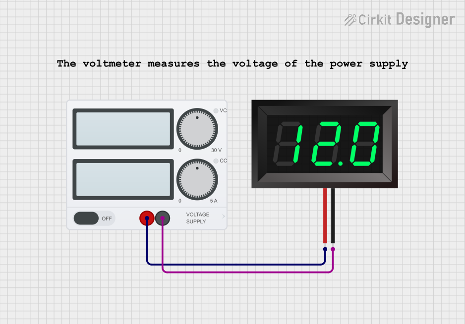
The 0-5V Voltmeter (Manufacturer: ELECALL, Part ID: 44C2) is a compact and reliable device designed to measure voltage levels within the range of 0 to 5 volts. It provides a clear and accurate visual display of the measured voltage, making it an essential tool for monitoring and debugging electronic circuits. This voltmeter is ideal for applications requiring real-time voltage monitoring, such as battery-powered systems, microcontroller-based projects, and power supply testing.
Explore Projects Built with 0-5V Voltmeter
Explore Projects Built with 0-5V Voltmeter
Common Applications and Use Cases
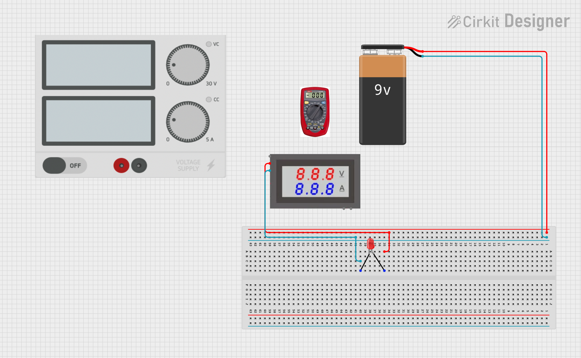
- Monitoring voltage levels in battery-powered devices
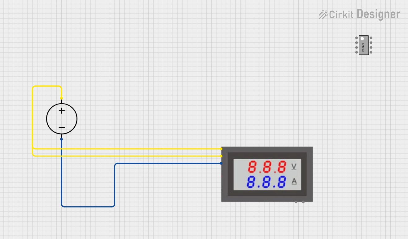
- Measuring output voltage of power supplies
- Debugging and testing electronic circuits
- Integrating into microcontroller projects for real-time voltage display
- Educational purposes in electronics labs
Technical Specifications
The following table outlines the key technical details of the ELECALL 44C2 0-5V Voltmeter:
| Parameter | Specification |
|---|---|
| Voltage Range | 0 to 5V |
| Display Type | 3-digit 7-segment LED |
| Input Impedance | ≥ 1MΩ |
| Accuracy | ±0.1V |
| Operating Voltage | 5V DC |
| Power Consumption | ≤ 20mA |
| Dimensions | 48mm x 29mm x 21mm |
| Operating Temperature | -10°C to 50°C |
| Mounting Type | Panel Mount |
Pin Configuration and Descriptions
The voltmeter has three pins for connection. The table below describes each pin:
| Pin | Name | Description |
|---|---|---|
| 1 | VCC | Positive power supply input (5V DC) |
| 2 | GND | Ground connection |
| 3 | VIN | Voltage input to be measured (0-5V range) |
Usage Instructions
How to Use the Component in a Circuit
- Power the Voltmeter: Connect the
VCCpin to a 5V DC power source and theGNDpin to the ground of the same power source. - Connect the Voltage to be Measured: Attach the voltage source (0-5V) to the
VINpin. Ensure the voltage does not exceed 5V to avoid damaging the device. - Read the Display: The measured voltage will be displayed on the 3-digit LED screen in real time.
Important Considerations and Best Practices
- Voltage Range: Ensure the input voltage to the
VINpin does not exceed 5V. Exceeding this limit may damage the voltmeter. - Power Supply: Use a stable 5V DC power source to power the voltmeter for accurate readings.
- Input Impedance: The high input impedance (≥ 1MΩ) ensures minimal current draw from the circuit being measured, but avoid connecting the voltmeter to high-impedance sources for extended periods.
- Mounting: Secure the voltmeter in a panel or enclosure to protect it from physical damage and environmental factors.
Example: Connecting to an Arduino UNO
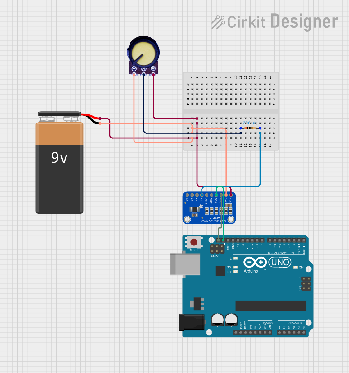
The 0-5V Voltmeter can be used with an Arduino UNO to measure and display the voltage of an analog signal. Below is an example circuit and code:
Circuit Connections
- Connect the
VCCpin of the voltmeter to the 5V pin of the Arduino. - Connect the
GNDpin of the voltmeter to the GND pin of the Arduino. - Connect the
VINpin of the voltmeter to the analog output signal you want to measure (e.g., a potentiometer connected to an analog pin).
Arduino Code
// Example code to read and display voltage using Arduino UNO
const int analogPin = A0;  // Analog pin connected to the voltage source
float voltage = 0.0;       // Variable to store the calculated voltage

void setup() {
  Serial.begin(9600);  // Initialize serial communication for debugging
}

void loop() {
  int sensorValue = analogRead(analogPin);  // Read the analog input
  voltage = sensorValue * (5.0 / 1023.0);  // Convert ADC value to voltage

  // Print the voltage to the Serial Monitor
  Serial.print("Voltage: ");
  Serial.print(voltage);
  Serial.println(" V");

  delay(500);  // Wait for 500ms before the next reading
}
Note: The voltmeter will display the voltage directly, while the Arduino can be used to log or process the voltage data further.
Troubleshooting and FAQs
Common Issues and Solutions
No Display on the Voltmeter
- Cause: The voltmeter is not receiving power.
- Solution: Check the connections to the
VCCandGNDpins. Ensure the power supply is providing 5V DC.
Incorrect Voltage Reading
- Cause: The input voltage exceeds the 0-5V range or there is noise in the circuit.
- Solution: Verify the input voltage is within the specified range. Use a stable power source and minimize noise in the circuit.
Flickering Display
- Cause: Unstable power supply or loose connections.
- Solution: Ensure the power supply is stable and all connections are secure.
Voltmeter Not Responding to Input Voltage
- Cause: Faulty
VINconnection or damaged device. - Solution: Check the
VINconnection and ensure the input voltage is within range. If the issue persists, the voltmeter may need to be replaced.
- Cause: Faulty
FAQs
Q1: Can the voltmeter measure negative voltages?
A1: No, the voltmeter is designed to measure voltages in the range of 0 to 5V only. Negative voltages or voltages exceeding 5V may damage the device.
Q2: Can I power the voltmeter with a voltage other than 5V?
A2: No, the voltmeter requires a stable 5V DC power supply for proper operation.
Q3: Is the voltmeter waterproof?
A3: No, the voltmeter is not waterproof. It should be used in dry environments and protected from moisture.
Q4: Can I use the voltmeter to measure AC voltage?
A4: No, the voltmeter is designed for DC voltage measurement only. Measuring AC voltage may damage the device.