How to Use JST-RCY_M: Examples, Pinouts, and Specs
Introduction
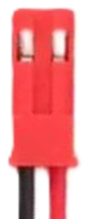
The JST-RCY_M is a compact and reliable electrical connector manufactured by JST. It is widely used in various electronic applications where secure and efficient connections are required. Its small form factor and robust design make it ideal for use in battery packs, RC (radio-controlled) devices, drones, and other portable electronic systems. The JST-RCY_M connector is known for its ease of use, durability, and ability to handle moderate current loads.
Explore Projects Built with JST-RCY_M

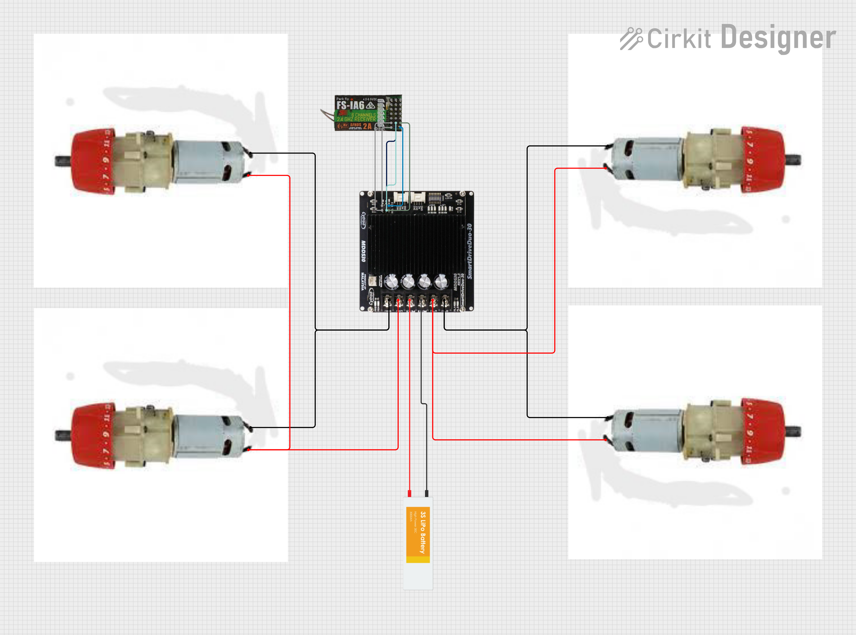

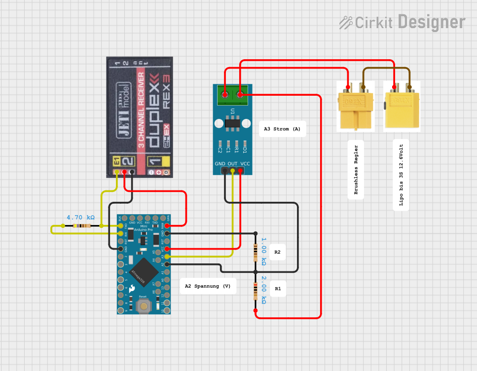
Explore Projects Built with JST-RCY_M
Common Applications
- Battery connections in RC vehicles, drones, and robotics
- Power delivery in portable electronic devices
- Connections in small-scale electronic projects
- Applications requiring quick and secure plug-and-play connections
Technical Specifications
The JST-RCY_M connector is designed to meet the needs of compact and reliable electrical connections. Below are its key technical specifications:
| Parameter | Specification |
|---|---|
| Manufacturer | JST |
| Part ID | JST-RCY_M |
| Connector Type | Wire-to-wire |
| Number of Contacts | 2 |
| Current Rating | Up to 3 Amperes |
| Voltage Rating | Up to 250 Volts |
| Wire Gauge Support | 22 AWG to 26 AWG |
| Operating Temperature | -25°C to +85°C |
| Housing Material | Nylon 66 (UL94V-0 flame retardant) |
| Contact Material | Phosphor bronze with tin plating |
Pin Configuration and Descriptions
The JST-RCY_M connector consists of two pins, typically used for power and ground connections. Below is the pin configuration:
| Pin Number | Name | Description |
|---|---|---|
| 1 | V+ | Positive voltage (power supply) |
| 2 | GND | Ground (return path for current) |
Usage Instructions
The JST-RCY_M connector is straightforward to use and can be integrated into a variety of electronic circuits. Follow the steps below to use the connector effectively:
Steps for Usage
- Wire Preparation: Strip the insulation from the ends of the wires you intend to connect. Ensure the exposed wire length matches the connector's crimp terminal specifications.
- Crimping: Use a compatible crimping tool to attach the crimp terminals to the wires. Ensure a secure and firm crimp to avoid loose connections.
- Insert Terminals: Insert the crimped terminals into the connector housing until they click into place. Verify that the terminals are locked securely.
- Mating: Connect the male and female JST-RCY_M connectors by aligning them and pushing them together until they snap into place.
- Testing: Verify the connection by testing the circuit for continuity and proper operation.
Important Considerations
- Wire Gauge: Use wires within the supported range (22 AWG to 26 AWG) to ensure proper crimping and electrical performance.
- Current Rating: Do not exceed the 3A current rating to avoid overheating or damage.
- Polarity: Always verify the polarity of the connections to prevent damage to the circuit or connected devices.
- Crimping Tool: Use a high-quality crimping tool designed for JST connectors to ensure reliable connections.
Example: Connecting to an Arduino UNO
The JST-RCY_M connector can be used to supply power to an Arduino UNO. Below is an example of how to connect a battery pack with a JST-RCY_M connector to the Arduino:
- Connect the positive wire (V+) from the JST-RCY_M connector to the Arduino's VIN pin.
- Connect the ground wire (GND) from the JST-RCY_M connector to the Arduino's GND pin.
Sample Code for Testing
// This code blinks an LED connected to pin 13 of the Arduino UNO.
// Ensure the Arduino is powered via the JST-RCY_M connector.

void setup() {
  pinMode(13, OUTPUT); // Set pin 13 as an output pin
}

void loop() {
  digitalWrite(13, HIGH); // Turn the LED on
  delay(1000);            // Wait for 1 second
  digitalWrite(13, LOW);  // Turn the LED off
  delay(1000);            // Wait for 1 second
}
Troubleshooting and FAQs
Common Issues
Loose Connections:
- Cause: Improper crimping or insertion of terminals.
- Solution: Re-crimp the terminals using a proper crimping tool and ensure they are securely locked into the housing.
Overheating:
- Cause: Exceeding the current rating of 3A.
- Solution: Reduce the current load or use a connector with a higher current rating.
Polarity Reversal:
- Cause: Incorrect wiring of the V+ and GND pins.
- Solution: Double-check the wiring and ensure the polarity matches the circuit requirements.
Connector Damage:
- Cause: Excessive force during mating or unmating.
- Solution: Handle the connector gently and avoid pulling on the wires.
FAQs
Q1: Can the JST-RCY_M connector be used for data transmission?
A1: No, the JST-RCY_M is primarily designed for power connections and is not suitable for high-speed data transmission.
Q2: What is the maximum wire length I can use with this connector?
A2: The maximum wire length depends on the current and voltage requirements of your application. For longer wires, ensure proper gauge and minimize resistance.
Q3: Can I solder wires directly to the connector instead of crimping?
A3: While possible, soldering is not recommended as it may compromise the connector's reliability and mechanical strength.
Q4: Is the JST-RCY_M connector waterproof?
A4: No, the JST-RCY_M connector is not waterproof. For outdoor or moisture-prone applications, consider using a waterproof connector.