How to Use Terminal PCB 2 Pin: Examples, Pinouts, and Specs
Introduction
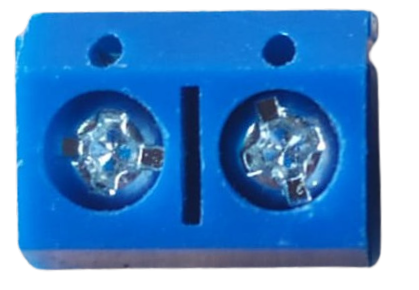
The Terminal PCB 2 Pin is a compact and reliable two-pin terminal block designed for use on printed circuit boards (PCBs). It provides a secure and convenient way to connect wires to a PCB, allowing for easy disconnection and reconnection without the need for soldering. This component is widely used in applications where modularity and ease of maintenance are essential.
Explore Projects Built with Terminal PCB 2 Pin


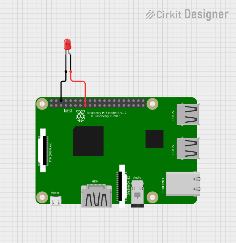

Explore Projects Built with Terminal PCB 2 Pin
Common Applications and Use Cases
- Power supply connections in electronic circuits
- Signal connections in control systems
- Prototyping and testing of PCB designs
- Industrial automation and equipment
- Home automation and IoT devices
Technical Specifications
The following table outlines the key technical details of the Terminal PCB 2 Pin:
| Parameter | Specification |
|---|---|
| Number of Pins | 2 |
| Rated Voltage | 300V |
| Rated Current | 10A |
| Wire Size Compatibility | 26-12 AWG |
| Pitch (Pin Spacing) | 5.08 mm (standard) |
| Material (Housing) | Polyamide (PA66), flame-retardant |
| Contact Material | Phosphor bronze with tin plating |
| Operating Temperature | -40°C to +105°C |
| Mounting Type | Through-hole |
Pin Configuration and Descriptions
The Terminal PCB 2 Pin has two pins for electrical connections. The table below describes the pin configuration:
| Pin Number | Description |
|---|---|
| 1 | Positive terminal (V+) |
| 2 | Negative terminal (V-) or GND |
Usage Instructions
How to Use the Component in a Circuit
Mounting the Terminal Block:
- Insert the pins of the terminal block into the corresponding through-hole pads on the PCB.
- Solder the pins securely to the PCB to ensure a stable connection.
Connecting Wires:
- Strip the insulation from the wire ends (approximately 5-7 mm).
- Insert the stripped wire ends into the terminal block's screw clamps.
- Tighten the screws using a small flathead screwdriver to secure the wires.
Testing the Connection:
- Verify the connection by gently tugging on the wires to ensure they are firmly secured.
- Use a multimeter to check for continuity if necessary.
Important Considerations and Best Practices
- Ensure the wire gauge is compatible with the terminal block (26-12 AWG).
- Avoid overtightening the screws, as this may damage the wire or the terminal block.
- Use proper insulation to prevent short circuits or accidental contact with other components.
- When designing the PCB, ensure the pin spacing (5.08 mm) matches the terminal block's pitch.
- For high-current applications, ensure the PCB traces are wide enough to handle the current.
Example: Connecting to an Arduino UNO
The Terminal PCB 2 Pin can be used to connect external power supplies or sensors to an Arduino UNO. Below is an example of how to use it for powering an Arduino UNO:
- Connect the positive terminal (V+) of the terminal block to the Arduino's VIN pin.
- Connect the negative terminal (V-) to the Arduino's GND pin.
// Example code for reading a sensor connected via Terminal PCB 2 Pin
// Ensure the sensor's V+ and GND are connected to the terminal block

const int sensorPin = A0; // Analog pin connected to the sensor output

void setup() {
  Serial.begin(9600); // Initialize serial communication
  pinMode(sensorPin, INPUT); // Set the sensor pin as input
}

void loop() {
  int sensorValue = analogRead(sensorPin); // Read the sensor value
  Serial.print("Sensor Value: ");
  Serial.println(sensorValue); // Print the sensor value to the Serial Monitor
  delay(1000); // Wait for 1 second before the next reading
}
Troubleshooting and FAQs
Common Issues Users Might Face
Loose Wire Connections:
- Cause: Screws are not tightened properly.
- Solution: Ensure the screws are securely tightened without damaging the wires.
Intermittent Connections:
- Cause: Poor soldering of the terminal block to the PCB.
- Solution: Re-solder the pins, ensuring a clean and solid joint.
Overheating of Terminal Block:
- Cause: Exceeding the rated current (10A).
- Solution: Ensure the current through the terminal block does not exceed its rated capacity.
Wire Slipping Out:
- Cause: Incorrect wire gauge or insufficient stripping of insulation.
- Solution: Use wires within the supported gauge range (26-12 AWG) and strip the insulation properly.
FAQs
Q1: Can I use this terminal block for AC connections?
A1: Yes, the Terminal PCB 2 Pin is rated for up to 300V, making it suitable for low-voltage AC applications. Ensure proper insulation and safety precautions.
Q2: Is this terminal block reusable?
A2: Yes, the terminal block allows for easy disconnection and reconnection of wires, making it reusable.
Q3: Can I use this terminal block for high-frequency signals?
A3: While it can handle low-frequency signals, it is not ideal for high-frequency applications due to potential signal degradation.
Q4: What tools are required to use this terminal block?
A4: You will need a small flathead screwdriver for tightening the screws and a soldering iron for mounting the terminal block to the PCB.
By following this documentation, you can effectively use the Terminal PCB 2 Pin in your electronic projects with confidence and ease.