How to Use Nucleo-L476RG: Examples, Pinouts, and Specs
Introduction
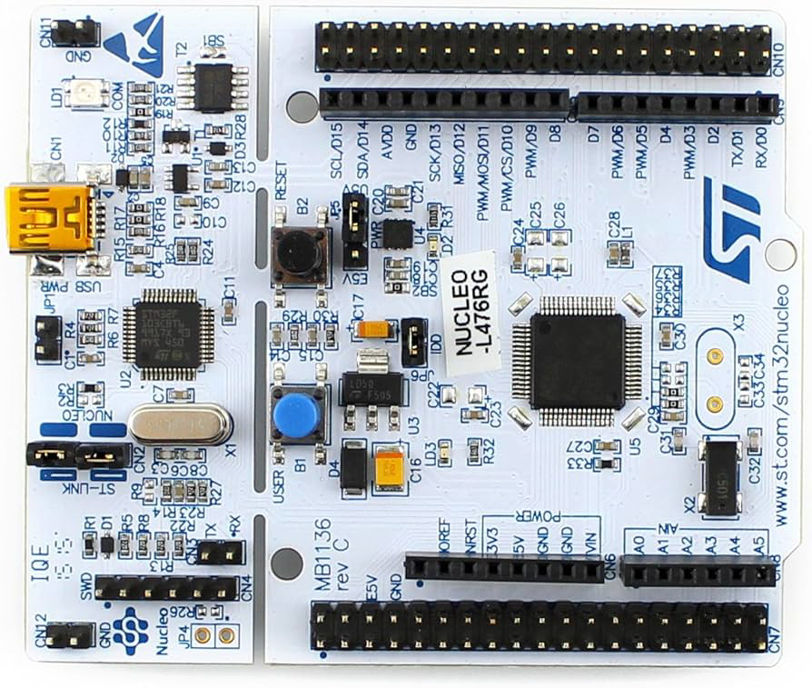
The Nucleo-L476RG is a development board built around the STM32L476RG microcontroller, which features an ARM Cortex-M4 core. This board is designed to provide a flexible and efficient platform for prototyping and developing embedded applications. It supports a wide range of peripherals, including digital and analog interfaces, and is compatible with Arduino Uno shields, making it highly versatile for various projects.
Explore Projects Built with Nucleo-L476RG

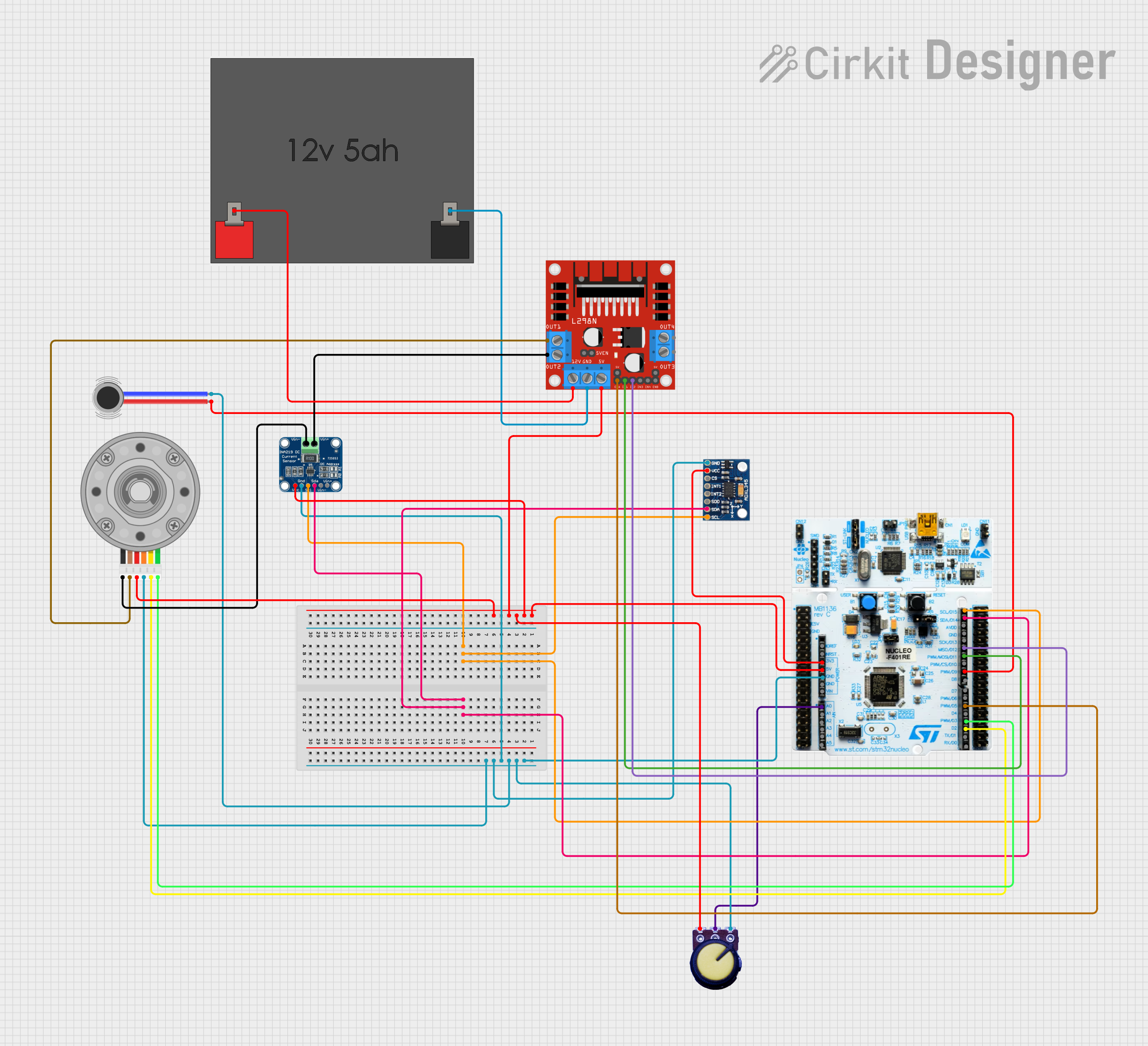
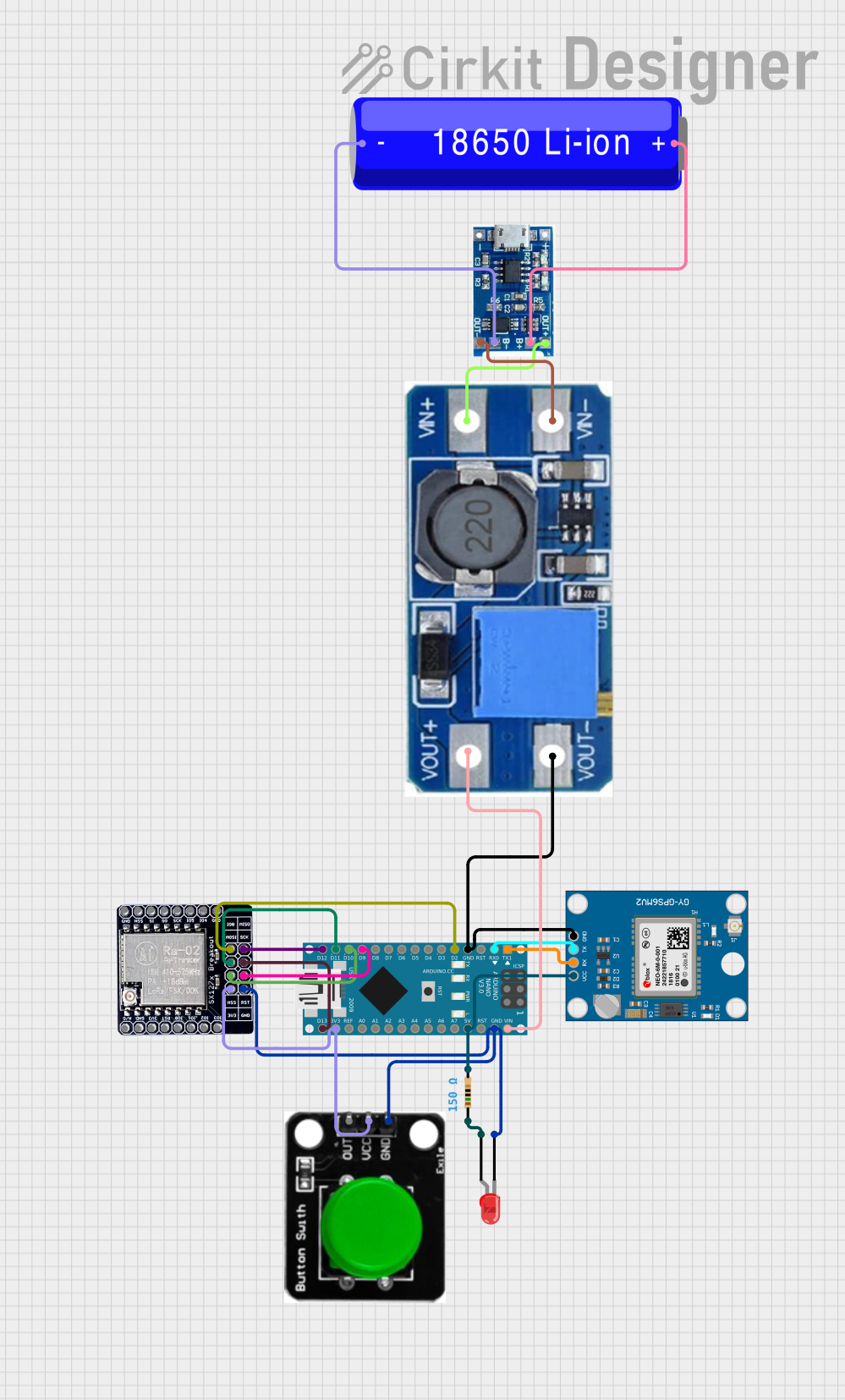
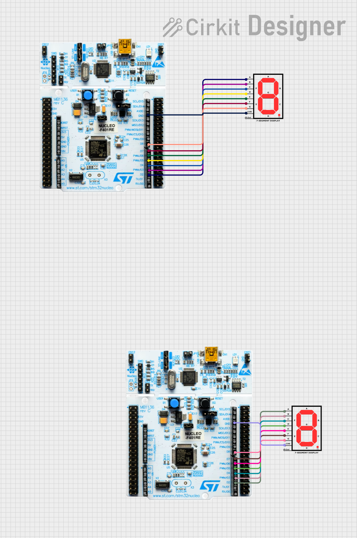
Explore Projects Built with Nucleo-L476RG
Common Applications and Use Cases
- Low-power IoT devices
- Wearable technology
- Sensor interfacing and data acquisition
- Prototyping with Arduino-compatible shields
- Educational and research projects in embedded systems
Technical Specifications
Key Technical Details
| Parameter | Specification |
|---|---|
| Microcontroller | STM32L476RG (ARM Cortex-M4 @ 80 MHz) |
| Flash Memory | 1 MB |
| SRAM | 128 KB |
| Operating Voltage | 3.3V |
| Input Voltage (VIN) | 7V to 12V |
| USB Interface | Micro-USB (for power and programming) |
| Clock Speed | 80 MHz |
| GPIO Pins | 51 |
| Analog Input Pins | 6 (12-bit ADC) |
| PWM Output Pins | 12 |
| Communication Interfaces | I2C, SPI, UART, CAN |
| Debug Interface | ST-LINK/V2-1 (onboard debugger) |
| Dimensions | 68.6 mm x 53.3 mm |
Pin Configuration and Descriptions
The Nucleo-L476RG features a dual-row pin header layout, compatible with Arduino Uno shields and ST morpho connectors. Below is a summary of the pin configuration:
Arduino-Compatible Header
| Pin Name | Functionality | Description |
|---|---|---|
| A0-A5 | Analog Inputs | 12-bit ADC channels |
| D0-D1 | UART (RX, TX) | Serial communication |
| D2-D13 | Digital I/O | GPIO, PWM (on select pins) |
| 3.3V | Power Output | 3.3V regulated output |
| 5V | Power Output | 5V regulated output |
| GND | Ground | Common ground |
| VIN | Power Input | External power supply input (7-12V) |
ST Morpho Connector
| Pin Name | Functionality | Description |
|---|---|---|
| PAx, PBx | GPIO, ADC, PWM, I2C, SPI, UART | Multi-purpose pins for peripherals |
| VDD | Power Supply | 3.3V power input/output |
| GND | Ground | Common ground |
Usage Instructions
How to Use the Nucleo-L476RG in a Circuit
Powering the Board:
- Connect the board to your computer via the Micro-USB port for power and programming.
- Alternatively, supply power through the VIN pin (7-12V) or the 5V pin (regulated 5V).
Programming the Board:
- Use the onboard ST-LINK/V2-1 debugger to program the STM32L476RG microcontroller.
- Compatible IDEs include STM32CubeIDE, Keil µVision, and IAR Embedded Workbench.
- For Arduino users, install the STM32 core in the Arduino IDE.
Connecting Peripherals:
- Use the Arduino-compatible headers for shields or connect sensors and actuators directly to the GPIO pins.
- For advanced peripherals, use the ST morpho connectors.
Running Your Code:
- After programming, the board will automatically reset and execute the uploaded firmware.
- Use the onboard LEDs (LD1, LD2) for debugging or status indication.
Important Considerations and Best Practices
- Ensure the input voltage does not exceed the specified range to avoid damaging the board.
- Use decoupling capacitors when connecting external components to reduce noise.
- Avoid connecting high-current loads directly to GPIO pins; use transistors or relays instead.
- When using the Arduino IDE, ensure the correct board and port are selected in the Tools menu.
Example Code for Arduino IDE
Below is an example of blinking the onboard LED (LD2) using the Arduino IDE:
// Define the pin connected to the onboard LED
#define LED_PIN LED_BUILTIN

void setup() {
  pinMode(LED_PIN, OUTPUT); // Set the LED pin as an output
}

void loop() {
  digitalWrite(LED_PIN, HIGH); // Turn the LED on
  delay(1000);                 // Wait for 1 second
  digitalWrite(LED_PIN, LOW);  // Turn the LED off
  delay(1000);                 // Wait for 1 second
}
Troubleshooting and FAQs
Common Issues and Solutions
The board is not detected by the computer:
- Ensure the USB cable is functional and supports data transfer.
- Check that the ST-LINK driver is installed on your computer.
Code does not upload to the board:
- Verify that the correct board and port are selected in the IDE.
- Ensure no other application is using the COM port.
- Press the reset button on the board before uploading.
Peripherals are not working as expected:
- Double-check the wiring and connections.
- Confirm that the correct pins are defined in your code.
- Use a multimeter to verify voltage levels at the pins.
The board overheats or does not power on:
- Ensure the input voltage is within the specified range (7-12V for VIN).
- Disconnect all peripherals and test the board with only USB power.
FAQs
Q: Can I use the Nucleo-L476RG with Arduino shields?
A: Yes, the board is compatible with most Arduino Uno shields via its Arduino-compatible headers.
Q: What is the maximum current output of the 3.3V and 5V pins?
A: The 3.3V pin can supply up to 150 mA, and the 5V pin can supply up to 500 mA when powered via USB.
Q: How do I reset the board?
A: Press the black reset button located near the Micro-USB port.
Q: Can I use the board for low-power applications?
A: Yes, the STM32L476RG microcontroller is optimized for low-power operation, making it suitable for battery-powered projects.