Cirkit Designer Logo
Cirkit Designer
Your all-in-one circuit design IDE
Home / 
Component Documentation

How to Use Adafruit UDA1334 I2S DAC: Examples, Pinouts, and Specs

Image of Adafruit UDA1334 I2S DAC
Cirkit Designer LogoDesign with Adafruit UDA1334 I2S DAC in Cirkit Designer

Introduction

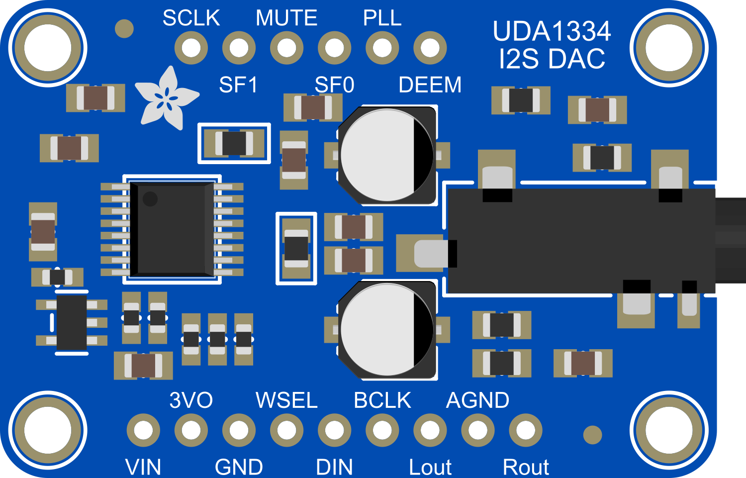
The Adafruit UDA1334 I2S DAC is a high-quality digital-to-analog converter designed to provide stereo audio output for microcontroller and Arduino-based projects. Utilizing the I2S (Inter-IC Sound) interface, this DAC is capable of delivering superior audio performance, making it an ideal choice for applications requiring sound playback such as MP3 players, synthesizers, and IoT devices with audio feedback.

Explore Projects Built with Adafruit UDA1334 I2S DAC

Use Cirkit Designer to design, explore, and prototype these projects online. Some projects support real-time simulation. Click "Open Project" to start designing instantly!
XIAO ESP32C3 Controlled I2S DAC Audio Interface
Image of Xiao_Dac: A project utilizing Adafruit UDA1334 I2S DAC in a practical application
This circuit connects an Adafruit UDA1334 I2S DAC to a XIAO ESP32C3 microcontroller for digital audio processing. The ESP32C3's GPIO pins are configured to interface with the DAC's I2S inputs for serial data, word select, and bit clock signals, enabling the microcontroller to send digital audio data to the DAC to be converted into analog signals. Power and ground connections are also established between the two components.
Cirkit Designer LogoOpen Project in Cirkit Designer
Raspberry Pi 5-Based Multi-Channel Audio System
Image of Noise Cancelling Project: A project utilizing Adafruit UDA1334 I2S DAC in a practical application
This circuit is an audio playback system that uses a Raspberry Pi 5 to process digital audio signals. The signals are sent to an I2S DAC and then amplified by PAM8302 amplifiers to drive two loudspeakers, providing stereo sound output.
Cirkit Designer LogoOpen Project in Cirkit Designer
Arduino UNO and MCP4725 DAC Module for Digital-to-Analog Conversion
Image of proses: A project utilizing Adafruit UDA1334 I2S DAC in a practical application
This circuit consists of an Arduino UNO microcontroller connected to an MCP4725 I2C DAC module. The Arduino UNO communicates with the DAC module via the I2C protocol to generate analog output signals.
Cirkit Designer LogoOpen Project in Cirkit Designer
Raspberry Pi 5 and Adafruit MCP4728 Based Digital-to-Analog Converter
Image of JUST: A project utilizing Adafruit UDA1334 I2S DAC in a practical application
This circuit connects a Raspberry Pi 5 to an Adafruit MCP4728 DAC via I2C communication. The Raspberry Pi provides power and ground to the DAC, and uses GPIO pins 2 and 3 for SDA and SCL lines respectively to control the DAC.
Cirkit Designer LogoOpen Project in Cirkit Designer

Explore Projects Built with Adafruit UDA1334 I2S DAC

Use Cirkit Designer to design, explore, and prototype these projects online. Some projects support real-time simulation. Click "Open Project" to start designing instantly!
Image of Xiao_Dac: A project utilizing Adafruit UDA1334 I2S DAC in a practical application
XIAO ESP32C3 Controlled I2S DAC Audio Interface
This circuit connects an Adafruit UDA1334 I2S DAC to a XIAO ESP32C3 microcontroller for digital audio processing. The ESP32C3's GPIO pins are configured to interface with the DAC's I2S inputs for serial data, word select, and bit clock signals, enabling the microcontroller to send digital audio data to the DAC to be converted into analog signals. Power and ground connections are also established between the two components.
Cirkit Designer LogoOpen Project in Cirkit Designer
Image of Noise Cancelling Project: A project utilizing Adafruit UDA1334 I2S DAC in a practical application
Raspberry Pi 5-Based Multi-Channel Audio System
This circuit is an audio playback system that uses a Raspberry Pi 5 to process digital audio signals. The signals are sent to an I2S DAC and then amplified by PAM8302 amplifiers to drive two loudspeakers, providing stereo sound output.
Cirkit Designer LogoOpen Project in Cirkit Designer
Image of proses: A project utilizing Adafruit UDA1334 I2S DAC in a practical application
Arduino UNO and MCP4725 DAC Module for Digital-to-Analog Conversion
This circuit consists of an Arduino UNO microcontroller connected to an MCP4725 I2C DAC module. The Arduino UNO communicates with the DAC module via the I2C protocol to generate analog output signals.
Cirkit Designer LogoOpen Project in Cirkit Designer
Image of JUST: A project utilizing Adafruit UDA1334 I2S DAC in a practical application
Raspberry Pi 5 and Adafruit MCP4728 Based Digital-to-Analog Converter
This circuit connects a Raspberry Pi 5 to an Adafruit MCP4728 DAC via I2C communication. The Raspberry Pi provides power and ground to the DAC, and uses GPIO pins 2 and 3 for SDA and SCL lines respectively to control the DAC.
Cirkit Designer LogoOpen Project in Cirkit Designer

Common Applications and Use Cases

  • DIY audio players
  • Home automation systems with voice output
  • Sound generation for games and interactive projects
  • Audio signal processing and output for musical instruments

Technical Specifications

Key Technical Details

  • Supply Voltage: 3.3V to 5V
  • Output: Stereo audio
  • Interface: I2S
  • Resolution: 24-bit
  • Sampling Rate: Up to 192kHz

Pin Configuration and Descriptions

Pin Number Name Description
1 VIN Power supply (3.3V to 5V)
2 GND Ground connection
3 LRC Left/Right Clock
4 BCLK Bit Clock
5 DIN Data Input
6 GAIN Gain Select (Low = 9dB, High = 12dB)
7 FMT Audio Data Format Select
8 SD Shutdown Control (Low = Shutdown)

Usage Instructions

How to Use the Component in a Circuit

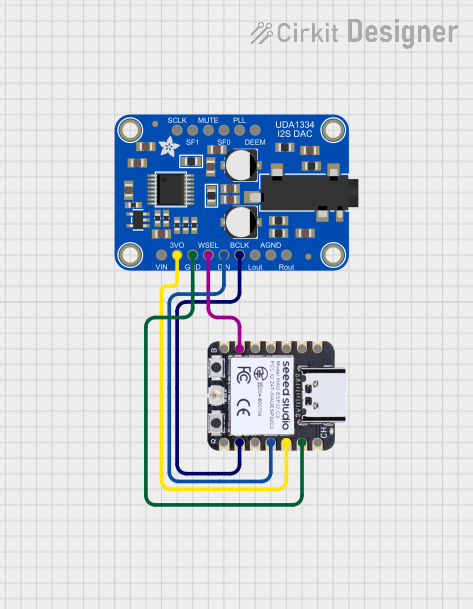
  1. Powering the DAC: Connect the VIN pin to a 3.3V or 5V power supply and the GND pin to the ground.

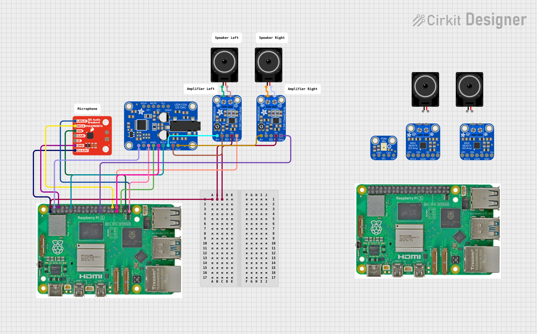
  2. Connecting I2S Signals: Connect the LRC, BCLK, and DIN pins to the corresponding I2S pins on your microcontroller or Arduino.

  3. Setting Gain and Format: Optionally, connect the GAIN pin to select the desired output gain and the FMT pin to set the audio data format.

  4. Shutdown Control: If you wish to control the power-down mode of the DAC, connect the SD pin to a digital output on your microcontroller.

Important Considerations and Best Practices

  • Ensure that the power supply is within the specified voltage range to prevent damage.
  • Use proper decoupling capacitors close to the power pins to minimize noise.
  • Keep the I2S signal lines as short as possible to reduce electromagnetic interference.
  • If you're using an Arduino, make sure to use a board or shield that supports I2S.

Example Code for Arduino UNO

#include <Wire.h>
#include <Adafruit_I2S.h>
#include <Adafruit_UDA1334.h>

// Create an instance of the UDA1334 class
Adafruit_UDA1334 dac = Adafruit_UDA1334();

void setup() {
  // Start the I2S interface
  if (!dac.begin()) {
    Serial.println("Failed to initialize DAC!");
    while (1);
  }
  Serial.println("DAC initialized.");
  
  // Optional: Set volume, etc.
}

void loop() {
  // Your code to play audio goes here
}

Troubleshooting and FAQs

Common Issues Users Might Face

  • No Audio Output: Ensure that all connections are secure and the I2S interface is properly initialized in your code.
  • Distorted Sound: Check the power supply for noise and ensure that the gain setting is appropriate for your speakers or amplifier.
  • Intermittent Sound: Verify that the I2S signal lines are not too long and are kept away from sources of electromagnetic interference.

Solutions and Tips for Troubleshooting

  • Double-check wiring against the pin configuration table.
  • Use a multimeter to verify that the power supply is within the correct range.
  • Ensure that the microcontroller's I2S pins are configured correctly in the software.
  • If using an Arduino, ensure that the library versions are compatible with your board.

FAQs

Q: Can the UDA1334 DAC be used with any microcontroller?

A: The DAC can be used with any microcontroller that supports the I2S protocol.

Q: What is the maximum audio quality achievable with this DAC?

A: The UDA1334 supports up to 24-bit resolution and a sampling rate of up to 192kHz, depending on the quality of the source audio and the capabilities of the microcontroller.

Q: Does the DAC require any additional components to function?

A: No additional components are necessary for basic operation, but decoupling capacitors and a clean power supply are recommended for best performance.

Q: How do I control the volume of the audio output?

A: Volume control can be implemented in software by adjusting the amplitude of the audio signal sent to the DAC.