How to Use DCF77 receiver: Examples, Pinouts, and Specs
Introduction
The DCF77 receiver is a specialized electronic component designed to receive time signals transmitted by the DCF77 radio station located in Mainflingen, Germany. The DCF77 station broadcasts highly accurate time and date information, synchronized with atomic clocks, over a longwave frequency of 77.5 kHz. This makes the DCF77 receiver an essential component for applications requiring precise timekeeping.
Explore Projects Built with DCF77 receiver

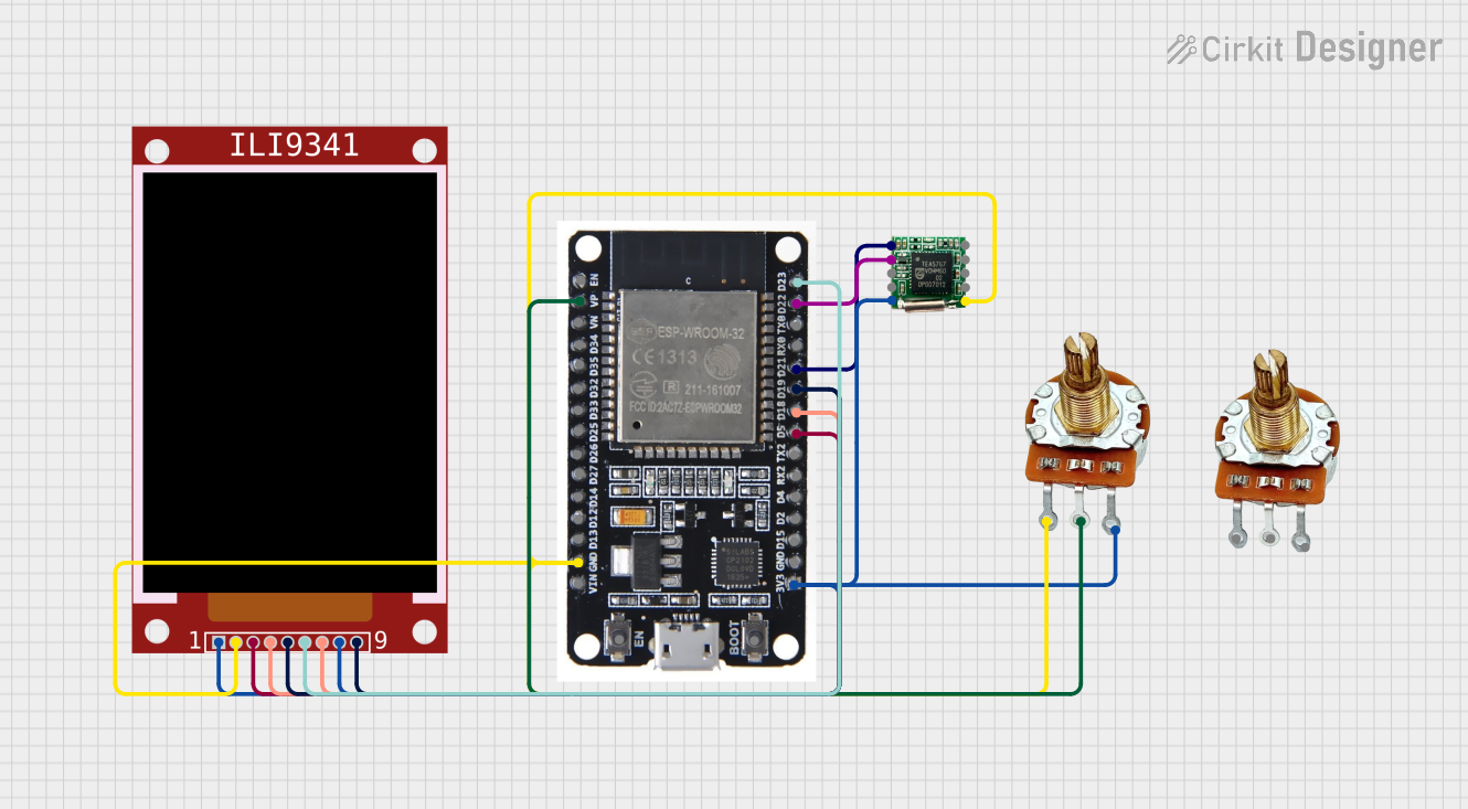

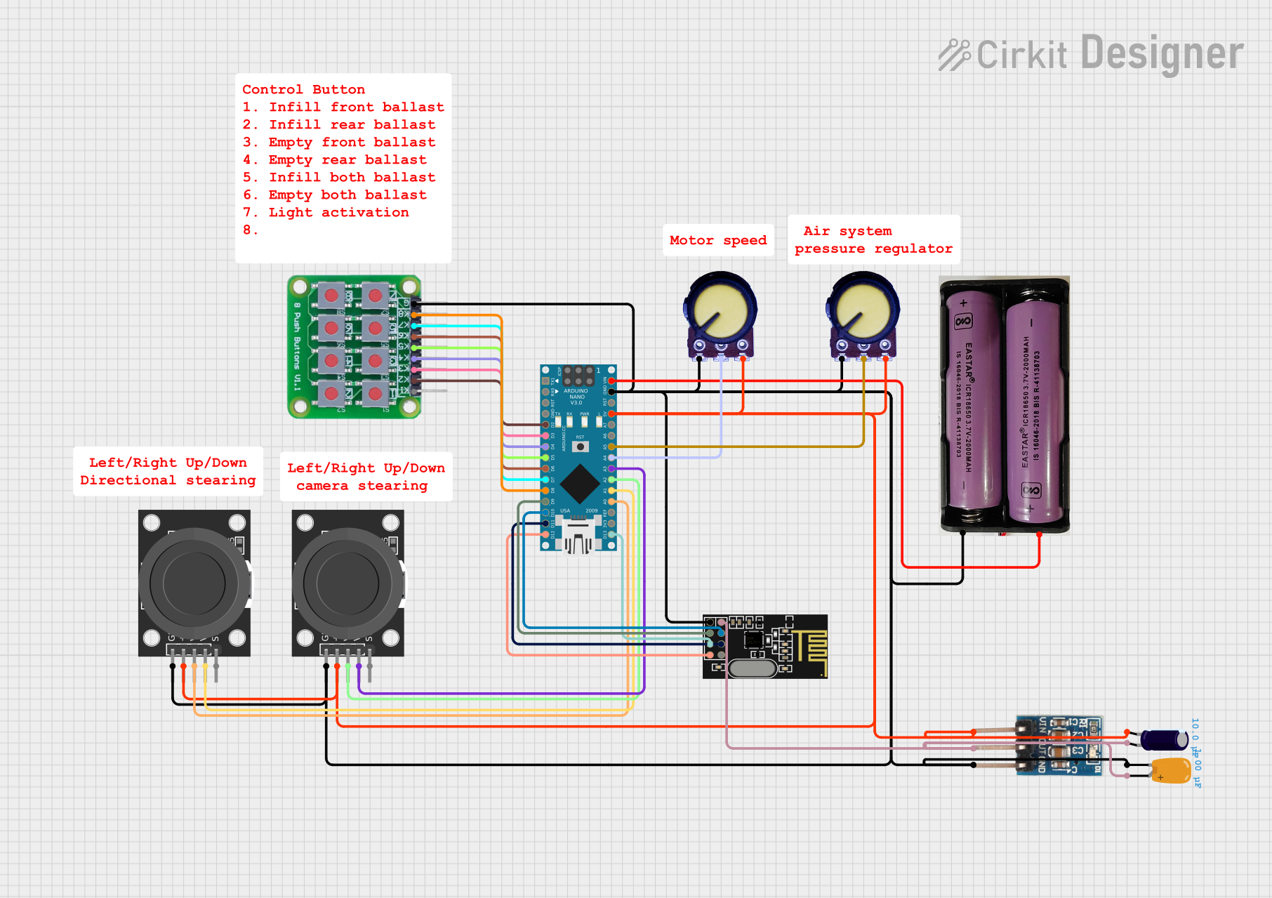
Explore Projects Built with DCF77 receiver
Common Applications and Use Cases
- Radio-controlled clocks and watches
- Industrial timing systems
- Home automation systems requiring synchronized time
- Data logging systems
- Time synchronization for embedded systems
Technical Specifications
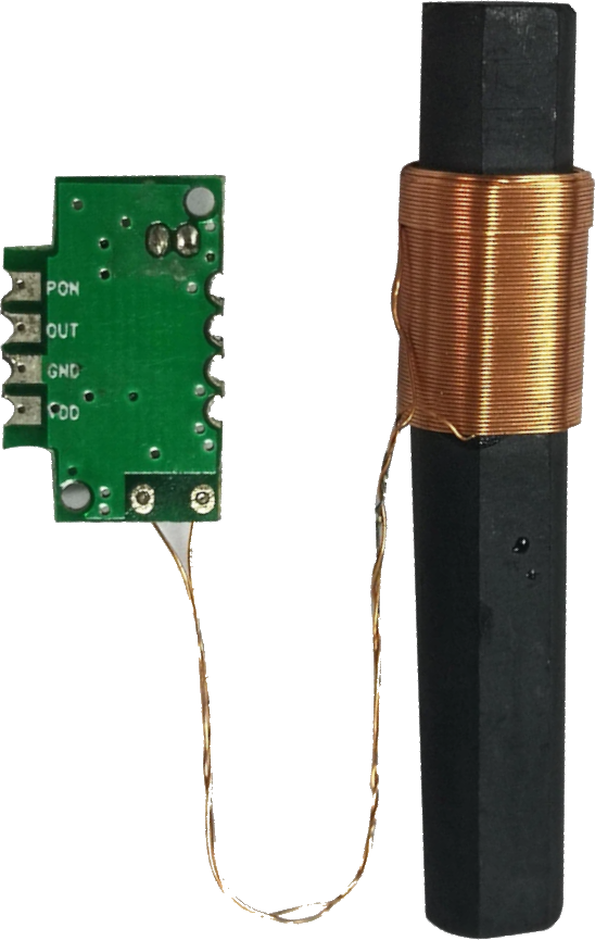
The DCF77 receiver module typically consists of an antenna, a signal amplifier, and a demodulator circuit. Below are the key technical details:
General Specifications
| Parameter | Value |
|---|---|
| Frequency | 77.5 kHz |
| Operating Voltage | 3.3V to 5V |
| Current Consumption | ~1 mA |
| Signal Output | Digital (Pulse Width Modulated) |
| Reception Range | Up to 2000 km (depending on conditions) |
| Antenna Type | Ferrite rod antenna |
Pin Configuration and Descriptions
| Pin Number | Pin Name | Description |
|---|---|---|
| 1 | VCC | Power supply input (3.3V to 5V). Provides power to the module. |
| 2 | GND | Ground connection. |
| 3 | DATA | Digital output pin. Outputs the demodulated time signal as a PWM signal. |
Usage Instructions
How to Use the DCF77 Receiver in a Circuit
- Power Supply: Connect the
VCCpin to a 3.3V or 5V power source and theGNDpin to the ground of your circuit. - Signal Output: Connect the
DATApin to a microcontroller or other digital input device capable of decoding the DCF77 signal. - Antenna Placement: Ensure the ferrite rod antenna is positioned away from sources of electromagnetic interference (e.g., power supplies, motors, or Wi-Fi routers) for optimal signal reception.
- Decoding the Signal: The DCF77 signal is transmitted as a series of pulses, where the pulse width encodes binary data (e.g., time, date, and status information). Use a microcontroller or dedicated DCF77 decoding library to interpret the signal.
Important Considerations and Best Practices
- Signal Reception: The DCF77 signal strength can vary depending on the time of day, weather conditions, and distance from the transmitter. Reception is typically better at night.
- Interference: Minimize interference by placing the receiver module away from electronic devices and metal enclosures.
- Decoding Software: Use a microcontroller with a DCF77 decoding library (e.g., Arduino DCF77 library) to simplify signal interpretation.
Example: Connecting to an Arduino UNO
Below is an example of how to connect and use the DCF77 receiver with an Arduino UNO:
Circuit Connections
| DCF77 Pin | Arduino Pin |
|---|---|
| VCC | 5V |
| GND | GND |
| DATA | Digital Pin 2 |
Arduino Code Example
#include <DCF77.h>
#include <TimeLib.h>
// Define the pin connected to the DCF77 DATA output
#define DCF77_PIN 2
#define DCF77_INTERRUPT 0 // Interrupt 0 corresponds to digital pin 2 on Arduino UNO
// Initialize the DCF77 object
DCF77 dcf77(DCF77_PIN, DCF77_INTERRUPT);
void setup() {
Serial.begin(9600);
Serial.println("Initializing DCF77 Receiver...");
// Start the DCF77 library
dcf77.Start();
}
void loop() {
// Check if a valid time signal has been received
time_t currentTime = dcf77.getTime();
if (currentTime != 0) {
// Print the synchronized time
Serial.print("Synchronized Time: ");
Serial.println(ctime(¤tTime));
} else {
// No valid signal received yet
Serial.println("Waiting for valid DCF77 signal...");
}
delay(1000); // Wait for 1 second before checking again
}
Notes on the Code
- The
DCF77library simplifies the process of decoding the time signal. - Ensure the Arduino is placed in an area with good signal reception for the DCF77 module.
Troubleshooting and FAQs
Common Issues and Solutions
No Signal Reception
- Cause: Poor antenna placement or interference.
- Solution: Move the receiver to a location with less interference and away from electronic devices.
Unstable or Incorrect Time
- Cause: Weak signal or decoding errors.
- Solution: Ensure the antenna is properly aligned and check for software updates to the decoding library.
Module Not Powering On
- Cause: Incorrect power supply voltage.
- Solution: Verify that the
VCCpin is connected to a 3.3V or 5V source.
FAQs
Q: Can the DCF77 receiver work outside of Europe?
A: The DCF77 signal is primarily intended for Europe, with a maximum range of approximately 2000 km from Germany. Reception outside this range is unlikely.
Q: How long does it take to synchronize the time?
A: Initial synchronization can take several minutes, depending on signal strength and environmental conditions.
Q: Can I use the DCF77 receiver indoors?
A: Yes, but signal reception may be weaker indoors. Place the module near a window for better results.
Q: What happens during signal interference?
A: The receiver may output incorrect or incomplete data. Use error-checking algorithms in your software to handle such cases.