How to Use 74HC4066N: Examples, Pinouts, and Specs
Introduction
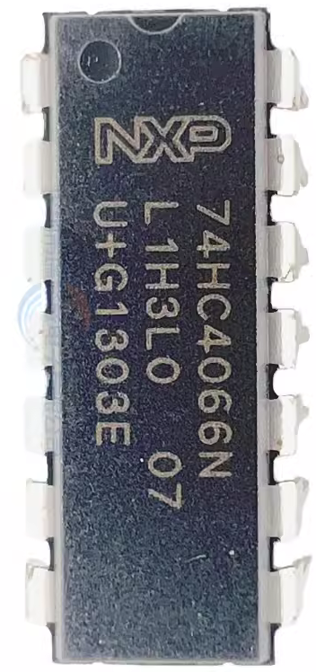
The 74HC4066N, manufactured by NXP, is a quad bilateral switch designed for the control of both analog and digital signals. Each switch in the IC can operate bidirectionally, allowing signals to pass in either direction when the control input is activated. The device is known for its low on-resistance, high-speed operation, and compatibility with a wide range of voltage levels.
Explore Projects Built with 74HC4066N


Explore Projects Built with 74HC4066N
Common Applications and Use Cases
- Signal routing and multiplexing
- Audio signal switching
- Analog-to-digital and digital-to-analog interfacing
- Data acquisition systems
- Test and measurement equipment
Technical Specifications
The following are the key technical details of the 74HC4066N:
- Supply Voltage (Vcc): 2V to 10V
- Control Input Voltage (VI): 0V to Vcc
- On-Resistance (RON): Typically 50Ω at Vcc = 5V
- Maximum Signal Voltage: 0V to Vcc
- Propagation Delay: ~3ns at Vcc = 5V
- Maximum Continuous Current (per switch): ±25mA
- Operating Temperature Range: -40°C to +125°C
- Package Type: DIP-14 (Dual In-line Package)
Pin Configuration and Descriptions
The 74HC4066N comes in a 14-pin DIP package. The pinout and descriptions are as follows:
| Pin Number | Pin Name | Description |
|---|---|---|
| 1 | 1C (Control 1) | Control input for switch 1. A HIGH signal enables the switch. |
| 2 | 1Y (I/O 1) | Input/Output terminal for switch 1. |
| 3 | 1Z (I/O 1) | Input/Output terminal for switch 1. |
| 4 | 2C (Control 2) | Control input for switch 2. A HIGH signal enables the switch. |
| 5 | 2Y (I/O 2) | Input/Output terminal for switch 2. |
| 6 | 2Z (I/O 2) | Input/Output terminal for switch 2. |
| 7 | GND | Ground (0V reference). |
| 8 | 3Z (I/O 3) | Input/Output terminal for switch 3. |
| 9 | 3Y (I/O 3) | Input/Output terminal for switch 3. |
| 10 | 3C (Control 3) | Control input for switch 3. A HIGH signal enables the switch. |
| 11 | 4Z (I/O 4) | Input/Output terminal for switch 4. |
| 12 | 4Y (I/O 4) | Input/Output terminal for switch 4. |
| 13 | 4C (Control 4) | Control input for switch 4. A HIGH signal enables the switch. |
| 14 | Vcc | Positive supply voltage. |
Usage Instructions
How to Use the 74HC4066N in a Circuit
- Power Supply: Connect the Vcc pin (pin 14) to a positive voltage source (2V to 10V) and the GND pin (pin 7) to ground.
- Control Inputs: Apply a HIGH signal (logic 1) to the control input pins (1C, 2C, 3C, 4C) to enable the corresponding switch. A LOW signal (logic 0) disables the switch.
- Signal Connections: Connect the signals to the I/O pins (1Y, 1Z, etc.). The signal can pass bidirectionally when the switch is enabled.
- Load Considerations: Ensure that the load connected to the switch does not exceed the maximum current rating of ±25mA.
Important Considerations and Best Practices
- Voltage Levels: Ensure that the signal voltage does not exceed the supply voltage (Vcc).
- On-Resistance: The on-resistance (RON) varies with the supply voltage. For minimal resistance, use a higher Vcc (e.g., 5V or 10V).
- Unused Pins: Leave unused control and I/O pins unconnected or tied to ground to avoid floating inputs.
- Decoupling Capacitor: Place a decoupling capacitor (e.g., 0.1µF) near the Vcc pin to stabilize the power supply.
Example: Connecting the 74HC4066N to an Arduino UNO
The 74HC4066N can be easily controlled using an Arduino UNO. Below is an example of how to toggle one of the switches using a digital pin.
Circuit Connections
- Connect Vcc (pin 14) to the Arduino's 5V pin.
- Connect GND (pin 7) to the Arduino's GND pin.
- Connect pin 1C (Control 1) to Arduino digital pin 8.
- Connect a signal source to pin 1Y and a load to pin 1Z.
Arduino Code
// Example code to control the 74HC4066N with an Arduino UNO
// This code toggles the first switch (1C) ON and OFF every second.

const int controlPin = 8; // Pin connected to 1C (Control 1)

void setup() {
  pinMode(controlPin, OUTPUT); // Set control pin as output
}

void loop() {
  digitalWrite(controlPin, HIGH); // Enable the switch
  delay(1000); // Wait for 1 second
  digitalWrite(controlPin, LOW); // Disable the switch
  delay(1000); // Wait for 1 second
}
Troubleshooting and FAQs
Common Issues and Solutions
Switch Not Activating:
- Cause: Control input is not receiving a HIGH signal.
- Solution: Verify the control input voltage. It should be at least 70% of Vcc for a HIGH signal.
Signal Distortion:
- Cause: Signal voltage exceeds the supply voltage or load impedance is too low.
- Solution: Ensure the signal voltage is within the range of 0V to Vcc and check the load impedance.
High On-Resistance:
- Cause: Low supply voltage (Vcc).
- Solution: Increase the supply voltage to reduce the on-resistance.
Floating Pins:
- Cause: Unused control or I/O pins are left floating.
- Solution: Tie unused pins to ground or a defined logic level.
FAQs
Q1: Can the 74HC4066N handle AC signals?
A1: Yes, the 74HC4066N can handle AC signals as long as the signal voltage remains within the range of 0V to Vcc.
Q2: What is the maximum frequency the 74HC4066N can switch?
A2: The maximum frequency depends on the supply voltage and load conditions. Typically, it can handle signals up to several MHz.
Q3: Can I use the 74HC4066N for audio applications?
A3: Yes, the low on-resistance and bidirectional switching make it suitable for audio signal routing and switching.
Q4: Is the 74HC4066N compatible with 3.3V logic?
A4: Yes, the 74HC4066N operates with supply voltages as low as 2V, making it compatible with 3.3V systems.