How to Use SIM A7670A Module: Examples, Pinouts, and Specs
Introduction
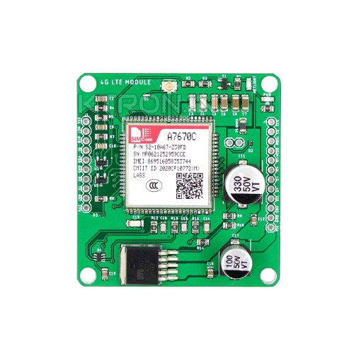
The SIM A7670A Module, manufactured by KTron, is a compact GSM/GPRS/EDGE module designed specifically for IoT applications. It provides reliable cellular connectivity for devices requiring low power consumption and high data rates. This module is ideal for applications such as smart meters, asset tracking, remote monitoring, and other IoT solutions where efficient and robust communication is essential.
Explore Projects Built with SIM A7670A Module


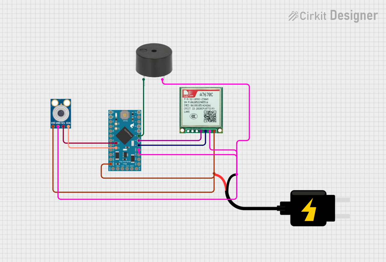
Explore Projects Built with SIM A7670A Module
Common Applications and Use Cases
- IoT Devices: Enables cellular connectivity for smart devices in remote locations.
- Asset Tracking: Provides real-time location and status updates for logistics and fleet management.
- Smart Meters: Facilitates data transmission for energy, water, and gas meters.
- Remote Monitoring: Supports applications like environmental monitoring and industrial automation.
- Wearable Devices: Powers compact, low-power communication for health and fitness trackers.
Technical Specifications
The SIM A7670A Module is designed to deliver high performance while maintaining low power consumption. Below are its key technical specifications:
General Specifications
| Parameter | Value |
|---|---|
| Manufacturer | KTron |
| Cellular Technology | GSM/GPRS/EDGE |
| Frequency Bands | GSM 850/900/1800/1900 MHz |
| Data Rates | GPRS: Up to 85.6 kbps (UL/DL) |
| Operating Voltage | 3.3V to 4.2V |
| Power Consumption | Idle: < 1mA, Active: ~500mA (peak) |
| Operating Temperature | -40°C to +85°C |
| Dimensions | 24mm x 24mm x 2.6mm |
Pin Configuration and Descriptions
The SIM A7670A Module features a 20-pin interface for easy integration into your circuit. Below is the pinout and description:
| Pin Number | Pin Name | Description |
|---|---|---|
| 1 | VCC | Power supply input (3.3V to 4.2V) |
| 2 | GND | Ground |
| 3 | TXD | UART Transmit Data |
| 4 | RXD | UART Receive Data |
| 5 | RTS | UART Request to Send |
| 6 | CTS | UART Clear to Send |
| 7 | DTR | Data Terminal Ready |
| 8 | RI | Ring Indicator |
| 9 | DCD | Data Carrier Detect |
| 10 | SIM_VCC | SIM card power supply |
| 11 | SIM_DATA | SIM card data line |
| 12 | SIM_CLK | SIM card clock line |
| 13 | SIM_RST | SIM card reset line |
| 14 | NET_STATUS | Network status indicator |
| 15 | PWRKEY | Power on/off control |
| 16 | RESET | Module reset |
| 17 | ADC | Analog-to-digital converter input |
| 18 | GPIO1 | General-purpose I/O pin |
| 19 | GPIO2 | General-purpose I/O pin |
| 20 | ANT | Antenna connection |
Usage Instructions
How to Use the SIM A7670A Module in a Circuit
- Power Supply: Connect the VCC pin to a regulated 3.3V-4.2V power source and GND to ground. Ensure the power supply can handle peak currents of up to 2A.
- UART Communication: Connect the TXD and RXD pins to the UART interface of your microcontroller (e.g., Arduino UNO). Use RTS and CTS for hardware flow control if required.
- SIM Card Interface: Insert a standard SIM card into the module's SIM card slot. Ensure proper connections to SIM_VCC, SIM_DATA, SIM_CLK, and SIM_RST.
- Antenna Connection: Attach a compatible GSM antenna to the ANT pin for optimal signal reception.
- Power On: Pull the PWRKEY pin low for at least 1 second to power on the module.
- Network Status: Monitor the NET_STATUS pin to check the module's connection to the cellular network.
Important Considerations and Best Practices
- Use decoupling capacitors near the VCC pin to stabilize the power supply.
- Ensure the antenna is properly matched to the module's frequency bands for optimal performance.
- Avoid placing the module near high-frequency noise sources to prevent interference.
- Use level shifters if interfacing with a 5V microcontroller, as the module operates at 3.3V logic levels.
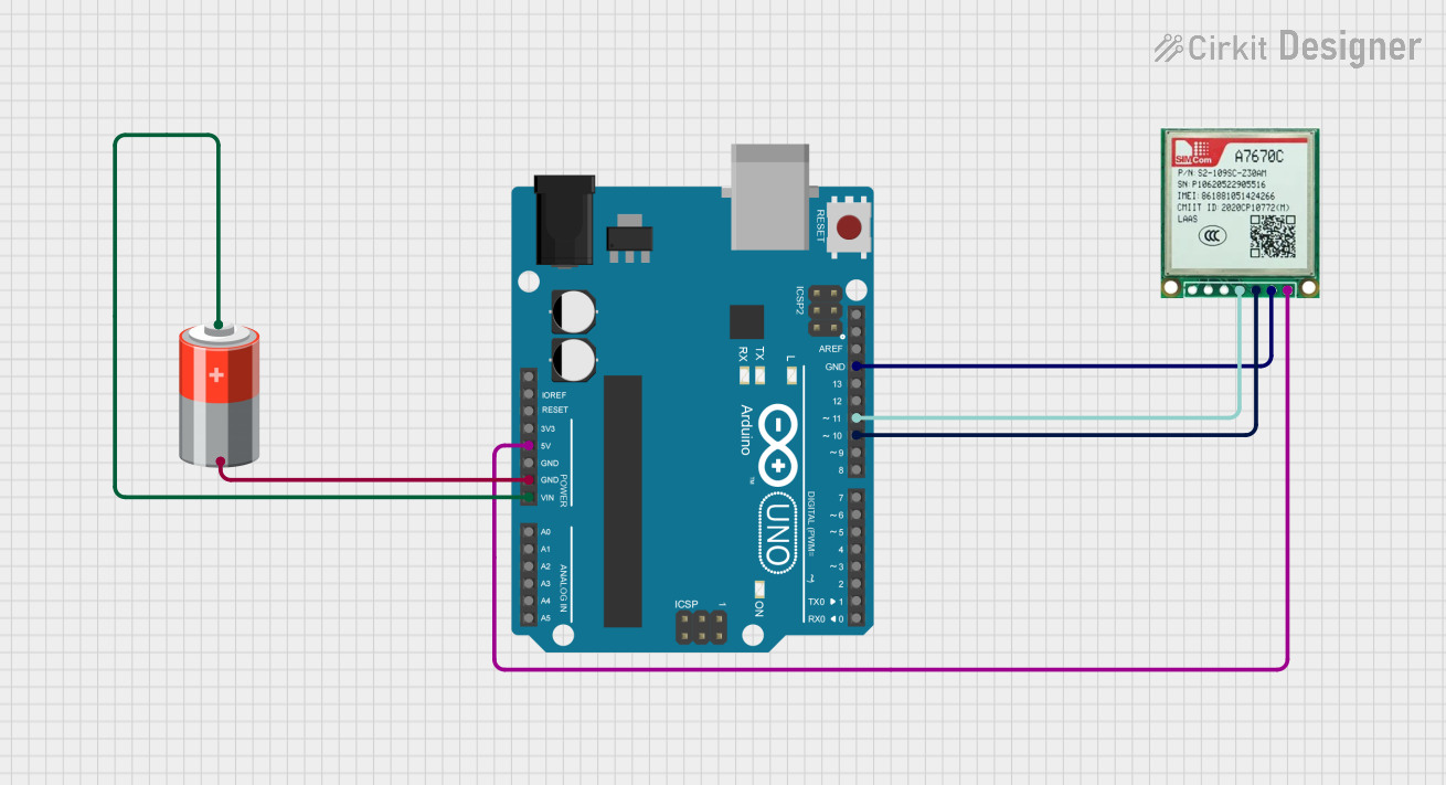
Example: Connecting to an Arduino UNO
Below is an example of how to interface the SIM A7670A Module with an Arduino UNO for sending an SMS:
Circuit Connections
| SIM A7670A Pin | Arduino UNO Pin |
|---|---|
| VCC | 3.3V |
| GND | GND |
| TXD | Pin 10 (RX) |
| RXD | Pin 11 (TX) |
| PWRKEY | Digital Pin 7 |
Arduino Code
#include <SoftwareSerial.h>

// Define software serial pins for communication with the SIM A7670A module
SoftwareSerial simModule(10, 11); // RX, TX

#define PWRKEY 7 // Power key pin

void setup() {
  pinMode(PWRKEY, OUTPUT);
  digitalWrite(PWRKEY, LOW); // Ensure PWRKEY is low initially
  delay(1000);
  digitalWrite(PWRKEY, HIGH); // Power on the module
  delay(2000);
  digitalWrite(PWRKEY, LOW);

  simModule.begin(9600); // Start communication with the module
  Serial.begin(9600);    // Start communication with the PC

  Serial.println("Initializing SIM A7670A Module...");
  delay(5000); // Wait for the module to initialize

  sendSMS("+1234567890", "Hello from SIM A7670A!");
}

void loop() {
  // Forward data from the module to the Serial Monitor
  if (simModule.available()) {
    Serial.write(simModule.read());
  }
  // Forward data from the Serial Monitor to the module
  if (Serial.available()) {
    simModule.write(Serial.read());
  }
}

void sendSMS(const char* phoneNumber, const char* message) {
  simModule.println("AT+CMGF=1"); // Set SMS mode to text
  delay(1000);
  simModule.print("AT+CMGS=\"");
  simModule.print(phoneNumber);
  simModule.println("\"");
  delay(1000);
  simModule.print(message);
  delay(1000);
  simModule.write(26); // Send Ctrl+Z to send the SMS
  delay(5000);
}
Troubleshooting and FAQs
Common Issues and Solutions
Module Not Powering On
- Ensure the PWRKEY pin is pulled low for at least 1 second during startup.
- Verify the power supply voltage is within the 3.3V-4.2V range and can handle peak currents.
No Network Connection
- Check the antenna connection and ensure it is compatible with the module's frequency bands.
- Verify the SIM card is active and has sufficient balance for data/SMS usage.
- Monitor the NET_STATUS pin for network status updates.
UART Communication Issues
- Ensure the baud rate of the microcontroller matches the module's default baud rate (9600 bps).
- Use level shifters if interfacing with a 5V microcontroller.
SMS Not Sending
- Confirm the SIM card supports SMS services and has sufficient balance.
- Ensure the phone number format is correct (e.g., include the country code).
FAQs
Q: Can the SIM A7670A Module be used for voice calls?
A: No, the SIM A7670A is designed for data and SMS communication only.
Q: What is the maximum data rate supported by the module?
A: The module supports GPRS data rates of up to 85.6 kbps for both uplink and downlink.
Q: Does the module support 4G networks?
A: No, the SIM A7670A is a GSM/GPRS/EDGE module and does not support 4G LTE networks.