How to Use 7404: Examples, Pinouts, and Specs
Introduction
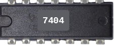
The 7404 is a hex inverter integrated circuit (IC) that contains six independent inverters. Each inverter takes a single input and produces an output that is the logical NOT of the input. This IC is part of the 7400 series of TTL (Transistor-Transistor Logic) devices, which are widely used in digital electronics. The 7404 is commonly employed in circuits where signal inversion is required, such as in logic gates, signal conditioning, and clock signal manipulation.
Explore Projects Built with 7404

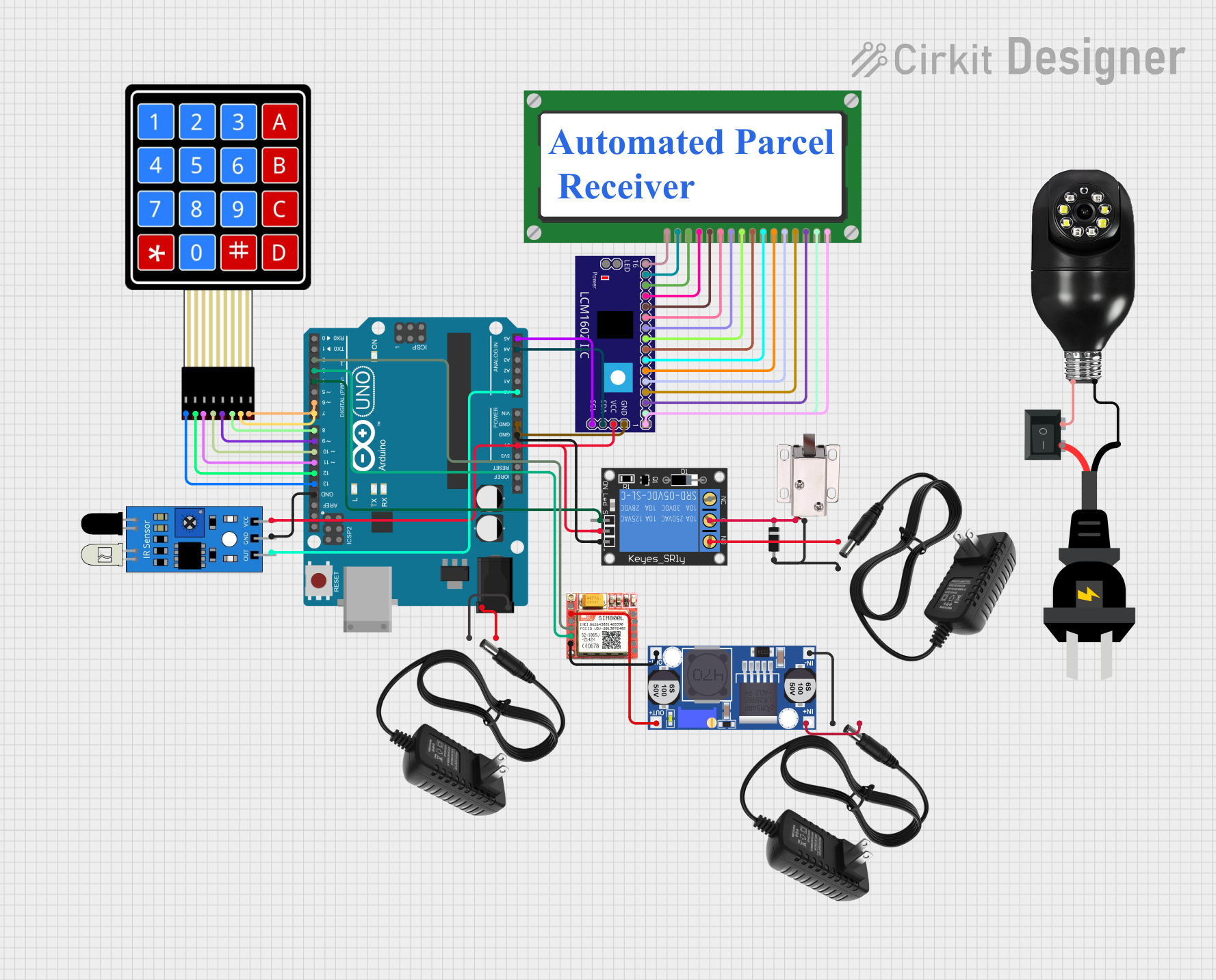


Explore Projects Built with 7404
Common Applications and Use Cases
- Logic level inversion in digital circuits
- Signal conditioning and noise reduction
- Clock signal inversion in timing circuits
- Implementation of NOT gates in combinational logic
- Used in microcontroller-based projects for signal processing
Technical Specifications
The 7404 IC is a TTL-based device with the following key specifications:
| Parameter | Value |
|---|---|
| Supply Voltage (Vcc) | 4.75V to 5.25V |
| Input Voltage (High) | 2.0V (minimum) |
| Input Voltage (Low) | 0.8V (maximum) |
| Output Voltage (High) | 2.4V (minimum) |
| Output Voltage (Low) | 0.4V (maximum) |
| Maximum Output Current | 16mA (per output) |
| Propagation Delay | ~10ns |
| Power Dissipation | 10mW (typical) |
| Operating Temperature | 0°C to 70°C |
| Package Types | DIP-14, SOIC-14, and others |
Pin Configuration and Descriptions
The 7404 IC is typically available in a 14-pin Dual Inline Package (DIP). The pinout is as follows:
| Pin Number | Pin Name | Description |
|---|---|---|
| 1 | A1 | Input to inverter 1 |
| 2 | Y1 | Output of inverter 1 |
| 3 | A2 | Input to inverter 2 |
| 4 | Y2 | Output of inverter 2 |
| 5 | A3 | Input to inverter 3 |
| 6 | Y3 | Output of inverter 3 |
| 7 | GND | Ground (0V) |
| 8 | Y4 | Output of inverter 4 |
| 9 | A4 | Input to inverter 4 |
| 10 | Y5 | Output of inverter 5 |
| 11 | A5 | Input to inverter 5 |
| 12 | Y6 | Output of inverter 6 |
| 13 | A6 | Input to inverter 6 |
| 14 | Vcc | Positive supply voltage (4.75V to 5.25V) |
Usage Instructions
How to Use the 7404 in a Circuit
- Power Supply: Connect pin 14 (Vcc) to a +5V power supply and pin 7 (GND) to ground.
- Input and Output: Connect the input signal to one of the input pins (A1 to A6). The corresponding output pin (Y1 to Y6) will provide the inverted signal.
- Load Considerations: Ensure that the output current does not exceed 16mA per pin to avoid damaging the IC.
- Bypass Capacitor: Place a 0.1µF ceramic capacitor between Vcc and GND to filter out noise and stabilize the power supply.
Example Circuit
Below is an example of using the 7404 to invert a digital signal:
- Input: A 5V square wave signal is applied to pin 1 (A1).
- Output: The inverted signal is observed at pin 2 (Y1).
+5V ----+------------------+
        |                  |
       [7404]             [LED]
        |                  |
       GND                GND
Using the 7404 with an Arduino UNO
The 7404 can be used with an Arduino UNO to invert a digital signal. For example, if you want to invert the state of a digital output pin, you can connect the Arduino pin to one of the 7404 inputs and read the inverted signal from the corresponding output.
Example Code
// Example: Using 7404 to invert a digital signal from Arduino UNO

const int inputPin = 2;  // Pin connected to 7404 input (e.g., A1)
const int outputPin = 3; // Pin connected to 7404 output (e.g., Y1)

void setup() {
  pinMode(inputPin, OUTPUT); // Set inputPin as output
  pinMode(outputPin, INPUT); // Set outputPin as input
}

void loop() {
  digitalWrite(inputPin, HIGH); // Send HIGH signal to 7404 input
  delay(1000);                 // Wait for 1 second
  digitalWrite(inputPin, LOW); // Send LOW signal to 7404 input
  delay(1000);                 // Wait for 1 second
}
Important Considerations and Best Practices
- Always use a bypass capacitor (0.1µF) near the IC to reduce noise.
- Avoid exceeding the maximum voltage and current ratings to prevent damage.
- Ensure proper grounding to avoid floating inputs, which can cause erratic behavior.
- Unused inputs should be tied to GND or Vcc to prevent noise interference.
Troubleshooting and FAQs
Common Issues and Solutions
No Output Signal:
- Check the power supply connections (Vcc and GND).
- Verify that the input signal is within the specified voltage range.
Erratic Output:
- Ensure that unused inputs are tied to GND or Vcc.
- Add a bypass capacitor between Vcc and GND to filter noise.
Overheating:
- Check if the output current exceeds the maximum rating (16mA per pin).
- Reduce the load on the output pins.
Incorrect Logic Levels:
- Verify the input and output connections.
- Ensure that the IC is not damaged by testing with a known good circuit.
FAQs
Q1: Can the 7404 operate at 3.3V?
A1: No, the 7404 is designed for TTL logic levels and requires a supply voltage between 4.75V and 5.25V.
Q2: Can I use multiple inverters simultaneously?
A2: Yes, all six inverters can be used independently, provided the total current does not exceed the IC's limits.
Q3: What happens if I leave an input pin floating?
A3: Floating inputs can cause erratic behavior. Always tie unused inputs to GND or Vcc.
Q4: Is the 7404 compatible with CMOS logic?
A4: The 7404 is a TTL device, but it can interface with CMOS logic if the voltage levels are compatible. Use level shifters if needed.