How to Use 35mm Piezo Transducer: Examples, Pinouts, and Specs
Introduction
The 35mm Piezo Transducer by MakerLab (Part ID: 35mm Piezo Transducer) is a versatile electronic component designed to convert electrical energy into mechanical vibrations. It operates based on the piezoelectric effect, where mechanical stress on specific materials generates an electrical charge. This transducer is widely used in applications such as sound generation, ultrasonic cleaning, and sensing.
Explore Projects Built with 35mm Piezo Transducer
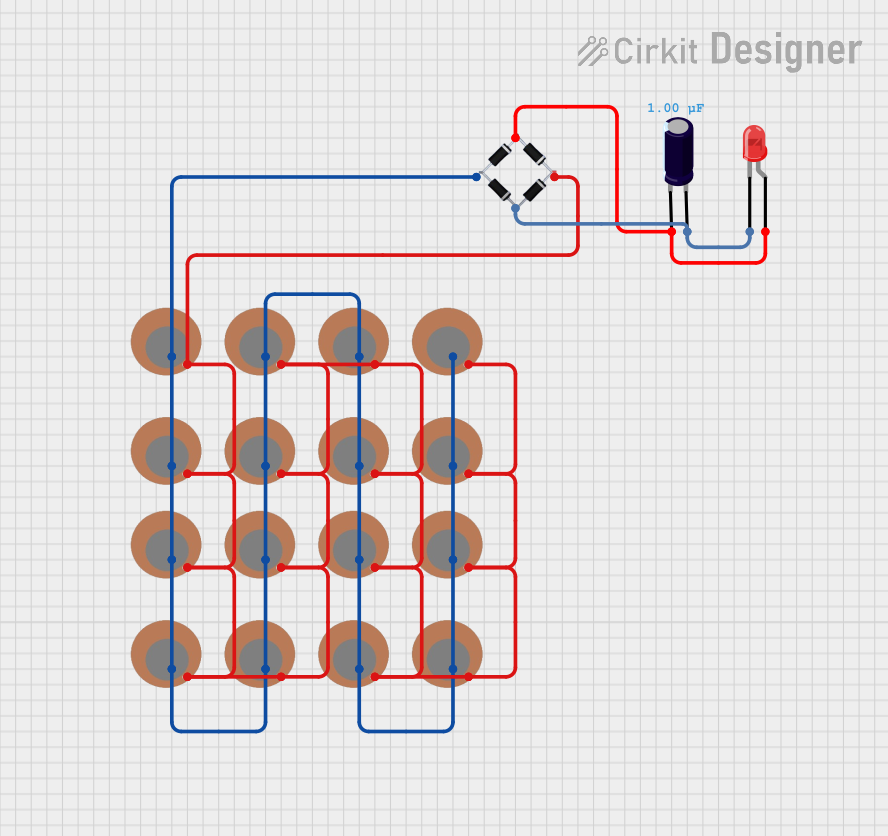
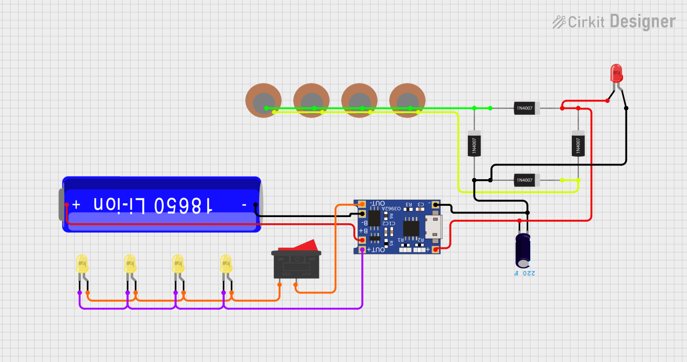
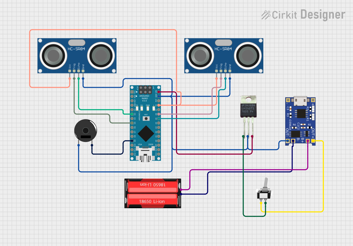
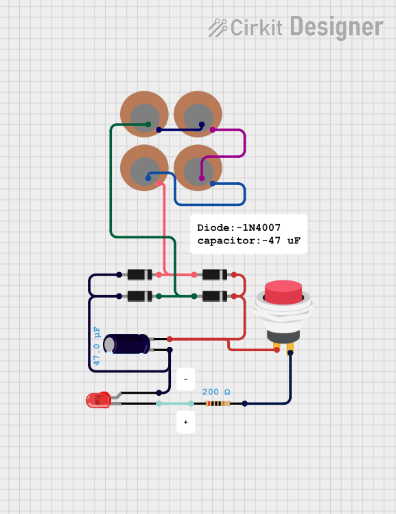
Explore Projects Built with 35mm Piezo Transducer
Common Applications:
- Sound Generation: Used in buzzers, alarms, and notification systems.
- Ultrasonic Cleaning: Generates high-frequency vibrations for cleaning delicate objects.
- Sensing: Detects vibrations, pressure, or sound waves in various systems.
- Musical Instruments: Functions as a pickup for acoustic instruments.
- Haptic Feedback: Provides tactile feedback in devices like touchscreens.
Technical Specifications
The following table outlines the key technical details of the 35mm Piezo Transducer:
| Parameter | Value |
|---|---|
| Manufacturer | MakerLab |
| Part ID | 35mm Piezo Transducer |
| Diameter | 35 mm |
| Operating Voltage | 3V to 30V |
| Resonant Frequency | ~4 kHz |
| Capacitance | ~20,000 pF (20 nF) |
| Operating Temperature | -20°C to +70°C |
| Material | Piezoelectric ceramic |
Pin Configuration and Descriptions
The 35mm Piezo Transducer typically has two terminals:
| Pin | Description |
|---|---|
| Positive (+) | Connects to the positive voltage supply. |
| Negative (-) | Connects to ground or the negative terminal. |
Usage Instructions
How to Use the 35mm Piezo Transducer in a Circuit
Basic Connection:
- Connect the positive terminal of the transducer to the output of a signal generator or microcontroller pin.
- Connect the negative terminal to the ground of the circuit.
- Use a current-limiting resistor (e.g., 1 kΩ) in series to protect the transducer and the driving circuit.
Driving with a Microcontroller:
- The transducer can be driven directly by a microcontroller like an Arduino UNO. However, for higher sound output, use a transistor or MOSFET as a driver.
Frequency Considerations:
- To achieve optimal performance, drive the transducer at its resonant frequency (~4 kHz). This can be done using a PWM signal from a microcontroller.
Example: Connecting to an Arduino UNO
Below is an example of how to use the 35mm Piezo Transducer with an Arduino UNO to generate a tone:
// Example: Generate a 4 kHz tone using Arduino UNO and 35mm Piezo Transducer

// Define the pin connected to the piezo transducer
const int piezoPin = 8;

void setup() {
  // Set the piezo pin as an output
  pinMode(piezoPin, OUTPUT);
}

void loop() {
  // Generate a 4 kHz tone for 500 milliseconds
  tone(piezoPin, 4000, 500);

  // Wait for 500 milliseconds before repeating
  delay(500);
}
Important Considerations and Best Practices
- Voltage Limits: Do not exceed the maximum operating voltage (30V) to avoid damaging the transducer.
- Frequency Matching: For maximum efficiency, drive the transducer at or near its resonant frequency.
- Mounting: Ensure the transducer is securely mounted to avoid unwanted vibrations or noise.
- Current Limiting: Always use a resistor in series to limit current and protect the circuit.
Troubleshooting and FAQs
Common Issues and Solutions
| Issue | Possible Cause | Solution |
|---|---|---|
| No sound or vibration | Incorrect wiring or insufficient voltage | Verify connections and ensure voltage is within the operating range. |
| Weak or distorted sound | Driving frequency is far from resonant freq. | Adjust the driving frequency closer to 4 kHz. |
| Overheating | Excessive voltage or current | Use a current-limiting resistor and ensure voltage is within limits. |
| Intermittent operation | Loose connections or poor soldering | Check and secure all connections. |
FAQs
Can I use the 35mm Piezo Transducer for sensing applications?
- Yes, the transducer can detect vibrations or sound waves when connected to an amplifier circuit.
What is the maximum sound output of this transducer?
- The sound output depends on the driving voltage and frequency. At its resonant frequency and maximum voltage, it can produce a loud tone suitable for alarms.
Can I drive the transducer directly from an Arduino pin?
- Yes, but for higher sound output, use a transistor or MOSFET as a driver.
How do I clean the transducer?
- Use a soft, dry cloth to clean the surface. Avoid using water or solvents that may damage the ceramic material.
By following this documentation, you can effectively integrate the MakerLab 35mm Piezo Transducer into your projects for sound generation, sensing, and more!