How to Use INA149: Examples, Pinouts, and Specs
Introduction
The INA149 is a precision instrumentation amplifier designed for low-power applications. It is specifically engineered to amplify small differential signals while rejecting large common-mode voltages. With its high input impedance, low offset voltage, and low noise characteristics, the INA149 is well-suited for applications requiring accurate signal amplification in challenging environments.
Explore Projects Built with INA149


Explore Projects Built with INA149
Common Applications and Use Cases
- Industrial process control
- Data acquisition systems
- Medical instrumentation
- High-voltage monitoring
- Precision measurement systems
- Bridge sensor amplification
Technical Specifications
The INA149 offers robust performance and is designed to handle a wide range of operating conditions. Below are the key technical specifications:
| Parameter | Value |
|---|---|
| Supply Voltage Range | ±2.25 V to ±18 V |
| Input Impedance | 10 GΩ (typical) |
| Common-Mode Voltage Range | ±275 V |
| Gain | Fixed at 1 V/V |
| Offset Voltage | ±1 mV (maximum) |
| Bandwidth | 500 kHz |
| Slew Rate | 1 V/μs |
| Quiescent Current | 700 μA (typical) |
| Operating Temperature Range | -40°C to +125°C |
Pin Configuration and Descriptions
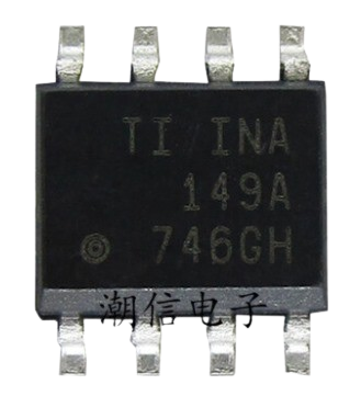
The INA149 is typically available in an 8-pin SOIC package. Below is the pinout and description:
| Pin Number | Pin Name | Description |
|---|---|---|
| 1 | -IN | Inverting input of the differential amplifier |
| 2 | +IN | Non-inverting input of the differential amplifier |
| 3 | V- | Negative power supply |
| 4 | REF | Reference voltage input |
| 5 | OUT | Amplifier output |
| 6 | NC | No connection (leave unconnected) |
| 7 | V+ | Positive power supply |
| 8 | NC | No connection (leave unconnected) |
Usage Instructions
The INA149 is straightforward to use in a circuit, but proper design considerations are essential to ensure optimal performance.
How to Use the INA149 in a Circuit
- Power Supply: Connect the V+ and V- pins to the appropriate positive and negative supply voltages. Ensure the supply voltage is within the specified range (±2.25 V to ±18 V).
- Input Signal: Connect the differential signal to the +IN and -IN pins. The INA149 can handle large common-mode voltages (up to ±275 V), but ensure the differential voltage is within the amplifier's linear range.
- Reference Voltage: The REF pin sets the output reference voltage. For single-supply operation, connect REF to mid-supply (e.g., V+/2). For dual-supply operation, REF is typically connected to ground.
- Output Signal: The amplified differential signal is available at the OUT pin. Connect this pin to the next stage of your circuit (e.g., an ADC or microcontroller).
Important Considerations and Best Practices
- Bypass Capacitors: Place decoupling capacitors (e.g., 0.1 μF and 10 μF) close to the V+ and V- pins to reduce power supply noise.
- Input Protection: If the input signals may exceed the INA149's input voltage range, use external resistors or diodes to protect the inputs.
- PCB Layout: Use a clean and low-noise PCB layout. Keep input traces short and away from noisy signals.
- Common-Mode Voltage: Ensure the common-mode voltage is within the specified range to avoid saturation or damage to the device.
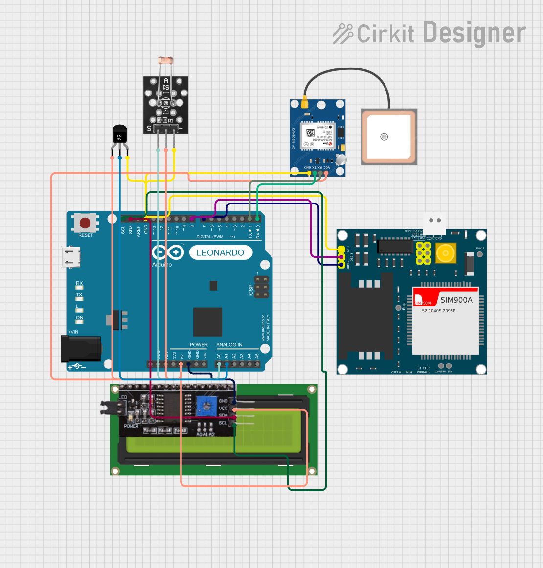
Example: Using the INA149 with an Arduino UNO
The INA149 can be used to amplify a small differential signal for measurement by an Arduino UNO's ADC. Below is an example circuit and code:
Circuit Description
- Connect the INA149's +IN and -IN pins to the differential signal source.
- Connect the REF pin to the Arduino's GND to set the output reference to 0 V.
- Connect the OUT pin to one of the Arduino's analog input pins (e.g., A0).
- Power the INA149 with a dual supply (e.g., ±12 V) or a single supply (e.g., 5 V and GND).
Arduino Code Example
// INA149 Example: Reading a differential signal with Arduino UNO
// Connect the INA149 OUT pin to Arduino analog pin A0

const int analogPin = A0; // Analog pin connected to INA149 OUT
float voltage = 0.0;      // Variable to store the measured voltage
const float vRef = 5.0;   // Arduino reference voltage (5V for default)

void setup() {
  Serial.begin(9600); // Initialize serial communication
}

void loop() {
  int adcValue = analogRead(analogPin); // Read ADC value (0-1023)

  // Convert ADC value to voltage
  voltage = (adcValue / 1023.0) * vRef;

  // Print the measured voltage
  Serial.print("Measured Voltage: ");
  Serial.print(voltage, 3); // Print voltage with 3 decimal places
  Serial.println(" V");

  delay(500); // Wait 500ms before the next reading
}
Troubleshooting and FAQs
Common Issues and Solutions
No Output Signal
- Cause: Incorrect power supply connections.
- Solution: Verify that V+ and V- are connected to the correct supply voltages.
Output Saturation
- Cause: Common-mode voltage exceeds the specified range.
- Solution: Ensure the common-mode voltage is within ±275 V.
High Noise on Output
- Cause: Insufficient power supply decoupling or noisy input signals.
- Solution: Add bypass capacitors near the power supply pins and use shielded cables for inputs.
Incorrect Output Voltage
- Cause: REF pin not properly connected.
- Solution: Verify the REF pin is connected to the desired reference voltage.
FAQs
Q: Can the INA149 be used with a single power supply?
A: Yes, the INA149 can operate with a single supply. Connect V- to GND and ensure the input and output signals remain within the device's operating range.
Q: What is the maximum differential input voltage?
A: The INA149 does not have a strict differential input voltage limit, but the output will saturate if the differential input exceeds the linear range of the amplifier.
Q: How do I handle high common-mode voltages?
A: The INA149 is designed to reject high common-mode voltages (up to ±275 V). Ensure the differential signal is within the linear range and the common-mode voltage does not exceed the specified limits.