How to Use buzzer: Examples, Pinouts, and Specs
Introduction
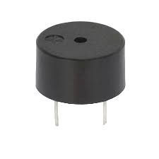
A buzzer is an audio signaling device that produces a buzzing sound when an electric current is applied. It is commonly used in alarms, timers, and confirmation of user input in electronic devices. Buzzers are essential components in various applications due to their simplicity, reliability, and ease of integration.
Explore Projects Built with buzzer
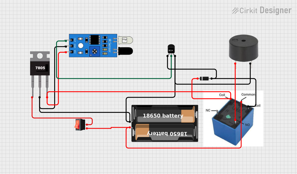
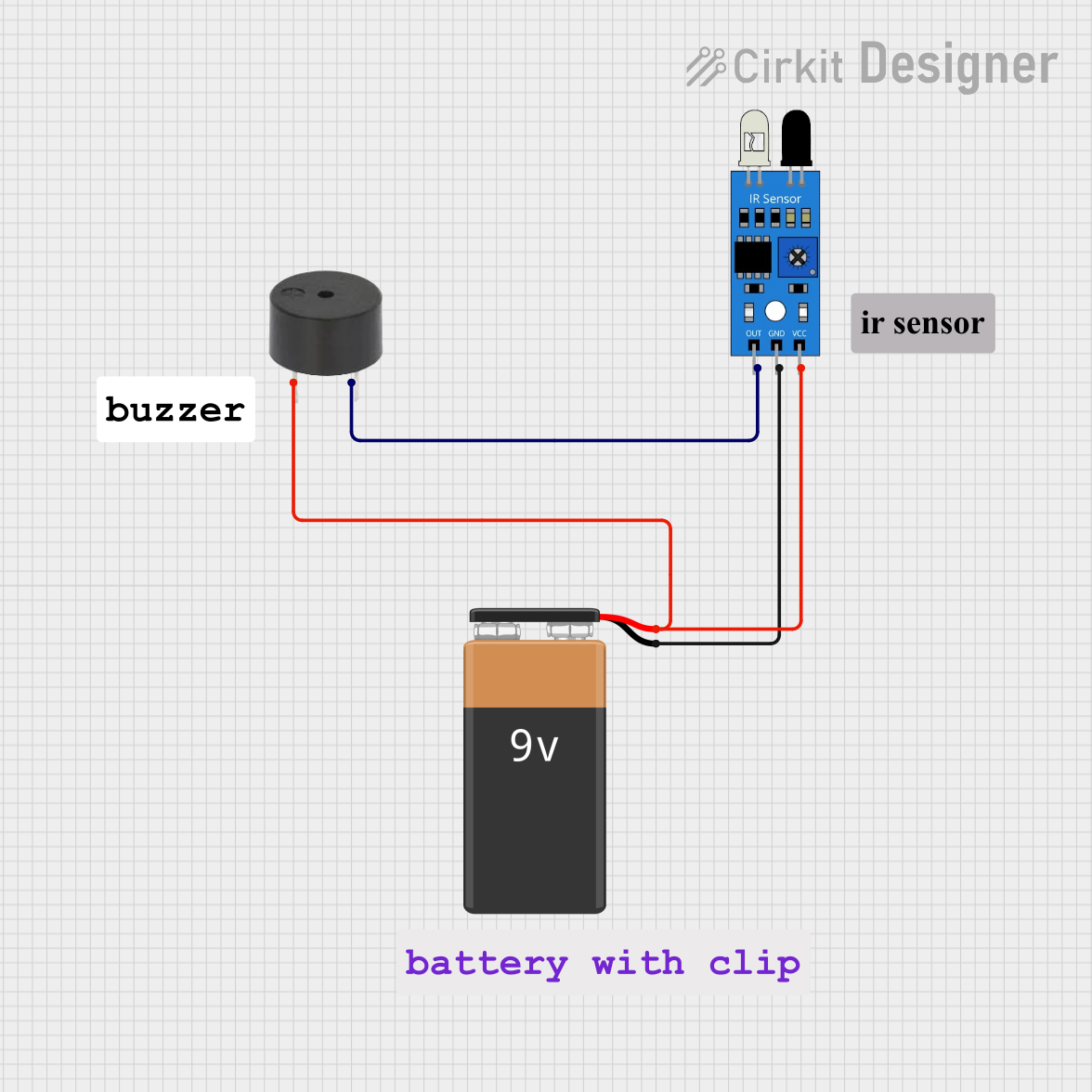

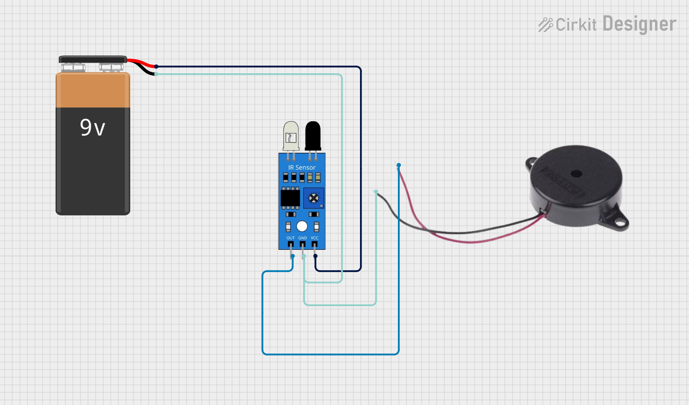
Explore Projects Built with buzzer
Common Applications and Use Cases
- Alarms and Alerts: Used in security systems, smoke detectors, and other alerting devices.
- Timers: Incorporated in kitchen timers, countdown timers, and other timing devices.
- User Input Confirmation: Provides audible feedback in devices like microwaves, washing machines, and other household appliances.
- Toys and Gadgets: Used in electronic toys and novelty items to produce sound effects.
Technical Specifications
Key Technical Details
| Parameter | Value |
|---|---|
| Operating Voltage | 3V to 12V |
| Current Consumption | 10mA to 30mA |
| Sound Output | 85dB at 10cm |
| Frequency | 2kHz to 4kHz |
| Operating Temperature | -20°C to +60°C |
| Dimensions | Varies (commonly 12mm diameter) |
Pin Configuration and Descriptions
| Pin Number | Pin Name | Description |
|---|---|---|
| 1 | VCC | Positive voltage supply (3V to 12V) |
| 2 | GND | Ground (0V) |
Usage Instructions
How to Use the Buzzer in a Circuit
- Connect the VCC Pin: Connect the VCC pin of the buzzer to the positive voltage supply (3V to 12V).
- Connect the GND Pin: Connect the GND pin of the buzzer to the ground (0V).
- Control the Buzzer: Use a microcontroller (e.g., Arduino UNO) or a simple switch to control the buzzer.
Important Considerations and Best Practices
- Voltage Range: Ensure the operating voltage is within the specified range (3V to 12V) to avoid damaging the buzzer.
- Current Limiting: Use a current-limiting resistor if necessary to prevent excessive current draw.
- Mounting: Secure the buzzer properly in your project to avoid mechanical vibrations affecting the sound quality.
- Polarity: Observe correct polarity when connecting the buzzer to avoid malfunction.
Example: Connecting a Buzzer to an Arduino UNO
Circuit Diagram
Arduino UNO          Buzzer
   5V  -------------- VCC
  GND  -------------- GND
  D8   -------------- Control Pin
Arduino Code
// Define the pin connected to the buzzer
const int buzzerPin = 8;

void setup() {
  // Set the buzzer pin as an output
  pinMode(buzzerPin, OUTPUT);
}

void loop() {
  // Turn the buzzer on
  digitalWrite(buzzerPin, HIGH);
  delay(1000); // Wait for 1 second

  // Turn the buzzer off
  digitalWrite(buzzerPin, LOW);
  delay(1000); // Wait for 1 second
}
Troubleshooting and FAQs
Common Issues Users Might Face
No Sound from Buzzer:
- Solution: Check the connections and ensure the buzzer is connected to the correct pins. Verify the power supply voltage is within the specified range.
Buzzer Produces Weak Sound:
- Solution: Ensure the power supply can provide sufficient current. Check for any loose connections or poor solder joints.
Buzzer Continuously Buzzes:
- Solution: Verify the control signal from the microcontroller or switch. Ensure the control logic is correctly implemented.
FAQs
Q1: Can I use a buzzer with a different voltage rating?
- A1: It is recommended to use a buzzer within its specified voltage range (3V to 12V) to ensure proper operation and avoid damage.
Q2: How can I adjust the volume of the buzzer?
- A2: The volume of the buzzer is generally fixed. However, you can use a PWM signal to control the duty cycle, which can indirectly affect the perceived volume.
Q3: Can I use a buzzer with an AC power supply?
- A3: No, buzzers are designed for DC power supply. Using an AC power supply can damage the buzzer.
Q4: What is the difference between a passive and an active buzzer?
- A4: An active buzzer has a built-in oscillator and produces sound when powered. A passive buzzer requires an external signal (e.g., PWM) to produce sound.
This documentation provides a comprehensive guide to understanding, using, and troubleshooting a buzzer in various electronic applications. Whether you are a beginner or an experienced user, this guide will help you effectively integrate a buzzer into your projects.