Cirkit Designer Logo
Cirkit Designer
Your all-in-one circuit design IDE
Home / 
Component Documentation

How to Use esp32-wroom 32u 38pins: Examples, Pinouts, and Specs

Image of esp32-wroom 32u 38pins
Cirkit Designer LogoDesign with esp32-wroom 32u 38pins in Cirkit Designer

Introduction

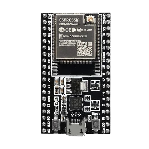
The ESP32-WROOM-32U is a high-performance microcontroller module manufactured by Pra with the part ID ESP32. It is designed for IoT (Internet of Things) applications, offering integrated Wi-Fi and Bluetooth capabilities. With its 38 pins, the module provides versatile connectivity options, making it suitable for a wide range of projects, from smart home devices to industrial automation.

Explore Projects Built with esp32-wroom 32u 38pins

Use Cirkit Designer to design, explore, and prototype these projects online. Some projects support real-time simulation. Click "Open Project" to start designing instantly!
ESP32-Based GPS Tracker with SD Card Logging and Barometric Sensor
Image of gps projekt circuit: A project utilizing esp32-wroom 32u 38pins in a practical application
This circuit features an ESP32 Wroom Dev Kit as the main microcontroller, interfaced with an MPL3115A2 sensor for pressure and temperature readings, and a Neo 6M GPS module for location tracking. The ESP32 is also connected to an SD card reader for data logging purposes. A voltage regulator is used to step down the USB power supply to 3.3V, which powers the ESP32, the sensor, and the SD card reader.
Cirkit Designer LogoOpen Project in Cirkit Designer
Raspberry Pi Pico and ESP32 Wi-Fi Controlled Sensor Interface
Image of pico_esp32: A project utilizing esp32-wroom 32u 38pins in a practical application
This circuit integrates a Raspberry Pi Pico and an ESP32 Wroom Dev Kit, interconnected through various GPIO pins and resistors, to enable communication and control between the two microcontrollers. The ESP32 is powered by a 3.3V supply and shares ground with the Raspberry Pi Pico, while specific GPIO pins are used for data exchange. The provided code sketches for the Raspberry Pi Pico suggest a framework for further development of the system's functionality.
Cirkit Designer LogoOpen Project in Cirkit Designer
ESP32-Based Multi-Sensor Health Monitoring System with Bluetooth Connectivity
Image of circuit diagram: A project utilizing esp32-wroom 32u 38pins in a practical application
This circuit features an ESP32-WROOM-32UE microcontroller as the central processing unit, interfacing with a variety of sensors and modules. It includes a MAX30100 pulse oximeter and heart-rate sensor, an MLX90614 infrared thermometer, an HC-05 Bluetooth module for wireless communication, and a Neo 6M GPS module for location tracking. All components are powered by a common voltage supply and are connected to specific GPIO pins on the ESP32 for data exchange, with the sensors using I2C communication and the modules using UART.
Cirkit Designer LogoOpen Project in Cirkit Designer
ESP32-Based Vibration Motor Controller with I2C IO Expansion
Image of VIBRATYION: A project utilizing esp32-wroom 32u 38pins in a practical application
This circuit features an ESP32 Wroom Dev Kit microcontroller interfaced with an MCP23017 I/O expansion board via I2C communication, utilizing GPIO 21 and GPIO 22 for SDA and SCL lines, respectively. A vibration motor is controlled by an NPN transistor acting as a switch, with a diode for back EMF protection and a resistor to limit base current. The ESP32 can control the motor by sending signals to the MCP23017, which then interfaces with the transistor to turn the motor on or off.
Cirkit Designer LogoOpen Project in Cirkit Designer

Explore Projects Built with esp32-wroom 32u 38pins

Use Cirkit Designer to design, explore, and prototype these projects online. Some projects support real-time simulation. Click "Open Project" to start designing instantly!
Image of gps projekt circuit: A project utilizing esp32-wroom 32u 38pins in a practical application
ESP32-Based GPS Tracker with SD Card Logging and Barometric Sensor
This circuit features an ESP32 Wroom Dev Kit as the main microcontroller, interfaced with an MPL3115A2 sensor for pressure and temperature readings, and a Neo 6M GPS module for location tracking. The ESP32 is also connected to an SD card reader for data logging purposes. A voltage regulator is used to step down the USB power supply to 3.3V, which powers the ESP32, the sensor, and the SD card reader.
Cirkit Designer LogoOpen Project in Cirkit Designer
Image of pico_esp32: A project utilizing esp32-wroom 32u 38pins in a practical application
Raspberry Pi Pico and ESP32 Wi-Fi Controlled Sensor Interface
This circuit integrates a Raspberry Pi Pico and an ESP32 Wroom Dev Kit, interconnected through various GPIO pins and resistors, to enable communication and control between the two microcontrollers. The ESP32 is powered by a 3.3V supply and shares ground with the Raspberry Pi Pico, while specific GPIO pins are used for data exchange. The provided code sketches for the Raspberry Pi Pico suggest a framework for further development of the system's functionality.
Cirkit Designer LogoOpen Project in Cirkit Designer
Image of circuit diagram: A project utilizing esp32-wroom 32u 38pins in a practical application
ESP32-Based Multi-Sensor Health Monitoring System with Bluetooth Connectivity
This circuit features an ESP32-WROOM-32UE microcontroller as the central processing unit, interfacing with a variety of sensors and modules. It includes a MAX30100 pulse oximeter and heart-rate sensor, an MLX90614 infrared thermometer, an HC-05 Bluetooth module for wireless communication, and a Neo 6M GPS module for location tracking. All components are powered by a common voltage supply and are connected to specific GPIO pins on the ESP32 for data exchange, with the sensors using I2C communication and the modules using UART.
Cirkit Designer LogoOpen Project in Cirkit Designer
Image of VIBRATYION: A project utilizing esp32-wroom 32u 38pins in a practical application
ESP32-Based Vibration Motor Controller with I2C IO Expansion
This circuit features an ESP32 Wroom Dev Kit microcontroller interfaced with an MCP23017 I/O expansion board via I2C communication, utilizing GPIO 21 and GPIO 22 for SDA and SCL lines, respectively. A vibration motor is controlled by an NPN transistor acting as a switch, with a diode for back EMF protection and a resistor to limit base current. The ESP32 can control the motor by sending signals to the MCP23017, which then interfaces with the transistor to turn the motor on or off.
Cirkit Designer LogoOpen Project in Cirkit Designer

Common Applications and Use Cases

  • IoT Devices: Smart home systems, environmental monitoring, and connected appliances.
  • Wearable Technology: Fitness trackers and health monitoring devices.
  • Industrial Automation: Remote monitoring and control systems.
  • Prototyping and Development: Ideal for hobbyists and engineers working on wireless communication projects.
  • Robotics: Wireless control and data transmission for robots and drones.

Technical Specifications

Key Technical Details

Parameter Value
Manufacturer Pra
Part ID ESP32
Wireless Connectivity Wi-Fi 802.11 b/g/n, Bluetooth v4.2 BR/EDR
Operating Voltage 3.0V to 3.6V
Flash Memory 4 MB (default)
SRAM 520 KB
GPIO Pins 38
CPU Dual-core Xtensa® 32-bit LX6
Clock Speed Up to 240 MHz
Operating Temperature -40°C to +85°C
Dimensions 18 mm x 25.5 mm

Pin Configuration and Descriptions

The ESP32-WROOM-32U module has 38 pins, each serving specific functions. Below is the pinout description:

Pin Number Pin Name Function Description
1 EN Enable pin. Active high to enable the module.
2 IO0 GPIO0, used for boot mode selection.
3 IO1 GPIO1, UART TXD (default).
4 IO2 GPIO2, general-purpose I/O.
5 IO3 GPIO3, UART RXD (default).
... ... ...
37 GND Ground pin.
38 3V3 3.3V power supply input.

Note: For the complete pinout, refer to the official datasheet provided by the manufacturer.


Usage Instructions

How to Use the ESP32-WROOM-32U in a Circuit

  1. Power Supply: Connect the 3.3V pin (Pin 38) to a stable 3.3V power source. Ensure the ground (GND) is connected to the circuit's ground.
  2. Boot Mode: To upload code, connect GPIO0 (Pin 2) to GND during reset. Disconnect it after uploading.
  3. Programming: Use a USB-to-Serial adapter to connect the module to your computer. The UART TXD and RXD pins (Pins 3 and 5) are used for communication.
  4. Peripherals: Connect sensors, actuators, or other peripherals to the GPIO pins as needed. Refer to the pinout table for specific pin functions.

Important Considerations and Best Practices

  • Voltage Levels: Ensure all connected devices operate at 3.3V logic levels to avoid damaging the module.
  • Antenna Placement: For optimal Wi-Fi and Bluetooth performance, ensure the onboard antenna is not obstructed by metal or other materials.
  • Heat Management: If operating in high-temperature environments, consider adding a heatsink or ensuring proper ventilation.
  • Firmware Updates: Regularly update the firmware to benefit from performance improvements and bug fixes.

Example: Connecting to an Arduino UNO

The ESP32-WROOM-32U can be programmed using the Arduino IDE. Below is an example code to connect the module to a Wi-Fi network:

#include <WiFi.h> // Include the WiFi library for ESP32

// Replace with your network credentials
const char* ssid = "Your_SSID";       // Your Wi-Fi network name
const char* password = "Your_PASSWORD"; // Your Wi-Fi password

void setup() {
  Serial.begin(115200); // Start serial communication at 115200 baud
  delay(1000);          // Wait for a second

  Serial.println("Connecting to Wi-Fi...");
  WiFi.begin(ssid, password); // Connect to the Wi-Fi network

  // Wait until the ESP32 is connected to Wi-Fi
  while (WiFi.status() != WL_CONNECTED) {
    delay(500);
    Serial.print(".");
  }

  Serial.println("\nConnected to Wi-Fi!");
  Serial.print("IP Address: ");
  Serial.println(WiFi.localIP()); // Print the assigned IP address
}

void loop() {
  // Add your main code here
}

Tip: Ensure the ESP32 board is selected in the Arduino IDE under Tools > Board.


Troubleshooting and FAQs

Common Issues and Solutions

  1. Module Not Powering On:

    • Cause: Insufficient power supply.
    • Solution: Ensure the power source provides a stable 3.3V with sufficient current (at least 500mA).
  2. Wi-Fi Connection Fails:

    • Cause: Incorrect SSID or password.
    • Solution: Double-check the credentials in your code. Ensure the Wi-Fi network is operational.
  3. Code Upload Fails:

    • Cause: Incorrect boot mode or serial port settings.
    • Solution: Ensure GPIO0 is connected to GND during reset. Verify the correct COM port and baud rate in the Arduino IDE.
  4. Overheating:

    • Cause: Prolonged high-performance operation.
    • Solution: Add a heatsink or improve ventilation around the module.

FAQs

  • Q: Can the ESP32-WROOM-32U operate on 5V?
    A: No, the module operates at 3.3V. Using 5V can damage the module.

  • Q: How do I reset the module?
    A: Pull the EN pin (Pin 1) low momentarily to reset the module.

  • Q: Can I use the ESP32-WROOM-32U with a battery?
    A: Yes, ensure the battery provides a stable 3.3V output.

  • Q: Is the module compatible with Bluetooth Low Energy (BLE)?
    A: Yes, the ESP32 supports both Bluetooth Classic and BLE.


This documentation provides a comprehensive guide to using the ESP32-WROOM-32U module. For further details, refer to the official datasheet or contact the manufacturer.