How to Use connector 1 in 2 out: Examples, Pinouts, and Specs
Introduction
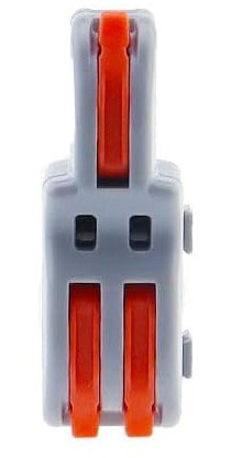
The Connector 1 In 2 Out is a versatile electronic component designed to split a single input signal into two identical output signals. It is commonly used in audio and video applications, where a single source needs to be distributed to multiple devices. This connector ensures minimal signal loss and maintains signal integrity, making it ideal for both professional and consumer-grade setups.
Explore Projects Built with connector 1 in 2 out


Explore Projects Built with connector 1 in 2 out
Common Applications and Use Cases
- Audio Systems: Splitting audio signals from a single source (e.g., a mixer or audio player) to two amplifiers or speakers.
- Video Distribution: Sending video signals from one source (e.g., a DVD player or camera) to two displays or monitors.
- Testing and Prototyping: Distributing signals in electronic testing environments.
- Home Entertainment Systems: Connecting a single media player to multiple TVs or sound systems.
Technical Specifications
The Connector 1 In 2 Out is a passive component, meaning it does not require external power to operate. Below are its key technical details:
General Specifications
| Parameter | Value |
|---|---|
| Input Signal Type | Analog or Digital (Audio/Video) |
| Output Signal Type | Analog or Digital (Audio/Video) |
| Signal Loss | ≤ 1 dB |
| Impedance | 50 Ω or 75 Ω (depending on model) |
| Connector Type | RCA, 3.5mm, HDMI, or BNC |
| Operating Temperature | -20°C to 70°C |
| Material | Gold-plated or nickel-plated pins |
Pin Configuration and Descriptions
The pin configuration depends on the type of connector used. Below is an example for a 3.5mm audio jack version:
| Pin Number | Name | Description |
|---|---|---|
| 1 | Input Signal | Receives the input signal from the source device |
| 2 | Output 1 | Sends the signal to the first output device |
| 3 | Output 2 | Sends the signal to the second output device |
| 4 | Ground | Common ground for input and output signals |
For other connector types (e.g., RCA or HDMI), refer to the specific pinout diagrams provided by the manufacturer.
Usage Instructions
How to Use the Connector in a Circuit
- Identify the Input and Outputs: Locate the input port (e.g., single RCA jack) and the two output ports (e.g., dual RCA jacks).
- Connect the Input Device: Plug the signal source (e.g., audio player or video camera) into the input port.
- Connect the Output Devices: Attach the two output devices (e.g., speakers, monitors) to the output ports.
- Verify Connections: Ensure all connections are secure to avoid signal loss or interference.
- Test the Setup: Power on the devices and verify that the signal is being transmitted to both outputs.
Important Considerations and Best Practices
- Signal Compatibility: Ensure the input and output devices are compatible with the connector's signal type (e.g., analog or digital).
- Impedance Matching: Use connectors with the appropriate impedance (50 Ω or 75 Ω) to minimize signal reflection and loss.
- Cable Quality: Use high-quality cables to maintain signal integrity, especially for high-frequency signals like HDMI.
- Avoid Overloading: Do not connect devices that draw excessive current or exceed the connector's specifications.
Example: Using the Connector with an Arduino UNO
While the Connector 1 In 2 Out is not directly programmable, it can be used in conjunction with an Arduino UNO to split signals from sensors or other input devices. Below is an example of splitting an analog signal from a potentiometer:
// Example: Reading a potentiometer signal and splitting it to two outputs
const int potPin = A0;  // Pin connected to the potentiometer
const int output1 = 9;  // First output pin
const int output2 = 10; // Second output pin

void setup() {
  pinMode(output1, OUTPUT); // Set output1 as an output
  pinMode(output2, OUTPUT); // Set output2 as an output
  Serial.begin(9600);       // Initialize serial communication
}

void loop() {
  int potValue = analogRead(potPin); // Read the potentiometer value
  int pwmValue = map(potValue, 0, 1023, 0, 255); // Map to PWM range (0-255)

  analogWrite(output1, pwmValue); // Send signal to output1
  analogWrite(output2, pwmValue); // Send signal to output2

  // Print the potentiometer value for debugging
  Serial.print("Potentiometer Value: ");
  Serial.println(potValue);

  delay(100); // Small delay for stability
}
Note: In this example, the Arduino UNO is used to read an analog signal and output it to two separate pins. The Connector 1 In 2 Out can then be used to distribute the signal further.
Troubleshooting and FAQs
Common Issues Users Might Face
Signal Loss or Degradation:
- Cause: Poor-quality cables or connectors, or excessive cable length.
- Solution: Use shorter, high-quality cables and ensure secure connections.
Uneven Signal Distribution:
- Cause: Impedance mismatch between the input and output devices.
- Solution: Use connectors with the correct impedance rating (50 Ω or 75 Ω).
No Signal on One Output:
- Cause: Faulty connector or improper connection.
- Solution: Test the connector with a multimeter and verify all connections.
Interference or Noise:
- Cause: Nearby electromagnetic interference (EMI) or poor grounding.
- Solution: Use shielded cables and ensure proper grounding.
FAQs
Q1: Can this connector be used for both analog and digital signals?
A1: Yes, the Connector 1 In 2 Out is compatible with both analog and digital signals, provided the devices and cables are suitable for the signal type.
Q2: Does this connector amplify the signal?
A2: No, this is a passive component and does not amplify the signal. For amplification, use an active splitter.
Q3: What is the maximum cable length I can use with this connector?
A3: The maximum cable length depends on the signal type and quality of the cables. For example, HDMI signals typically support up to 15 meters with standard cables.
Q4: Can I use this connector with a powered device?
A4: Yes, as long as the device's output signal is within the connector's specifications.
By following this documentation, users can effectively utilize the Connector 1 In 2 Out in their projects and troubleshoot common issues with ease.