
How to Use ULTASONIC: Examples, Pinouts, and Specs
 Design with ULTASONIC in Cirkit Designer
Introduction
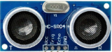
The ULTRASONIC sensor is a device that uses high-frequency sound waves to measure distances or detect objects in its surroundings. It operates by emitting ultrasonic waves and measuring the time it takes for the echo to return after bouncing off an object. This time-of-flight measurement is then used to calculate the distance to the object.
Common applications of the ULTRASONIC sensor include:
- Obstacle detection in robotics
- Distance measurement in automation systems
- Liquid level sensing in tanks
- Proximity detection in parking assistance systems
Explore Projects Built with ULTASONIC
 Open Project in Cirkit Designer
 Open Project in Cirkit Designer
 Open Project in Cirkit Designer
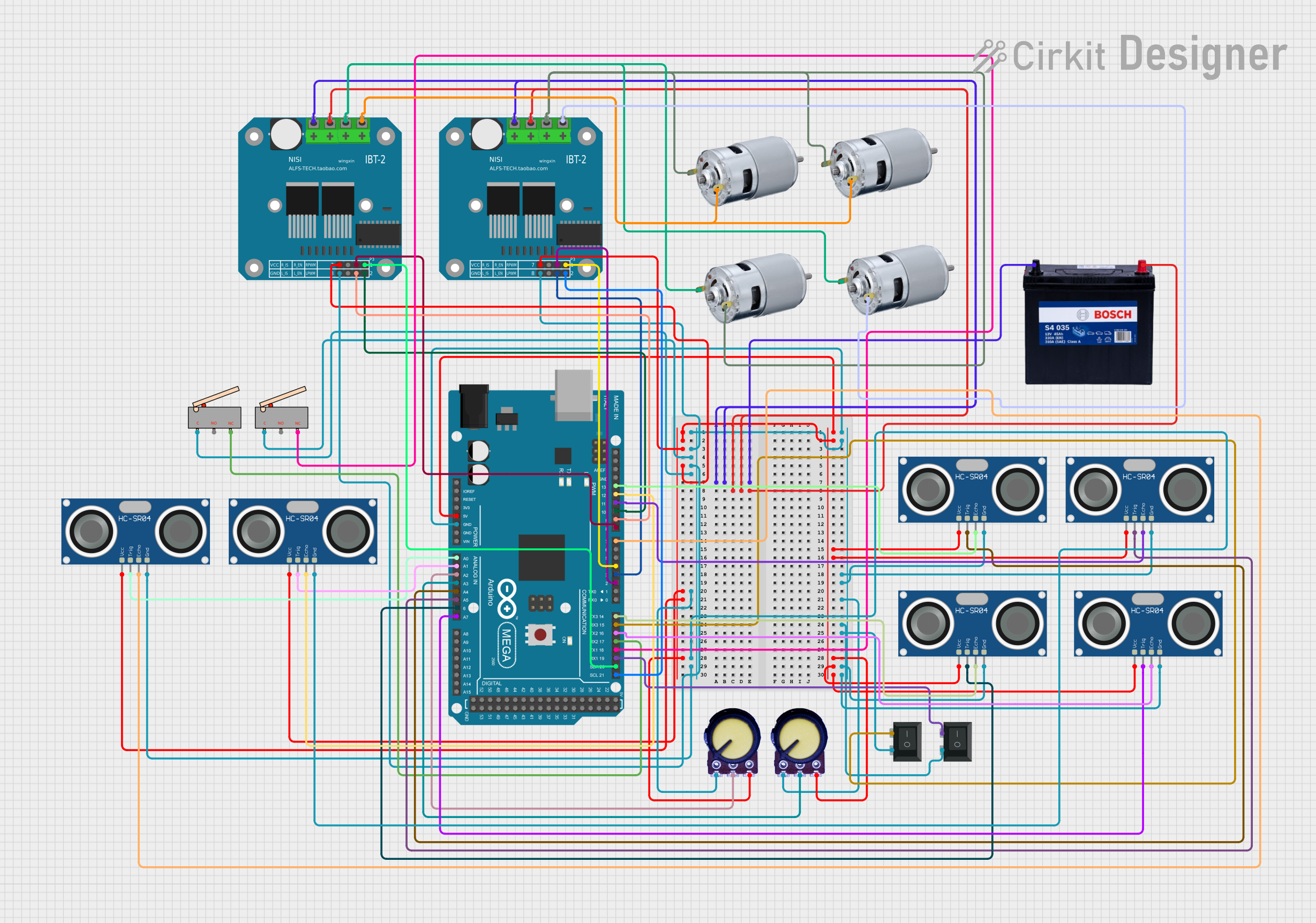 Open Project in Cirkit Designer
Explore Projects Built with ULTASONIC
Open Project in Cirkit DesignerOpen Project in Cirkit DesignerOpen Project in Cirkit DesignerOpen Project in Cirkit DesignerTechnical Specifications
The following are the key technical details of the ULTRASONIC sensor:
| Parameter | Value |
|---|---|
| Operating Voltage | 5V DC |
| Operating Current | < 15 mA |
| Measuring Range | 2 cm to 400 cm |
| Accuracy | ±3 mm |
| Operating Frequency | 40 kHz |
| Trigger Input Signal | 10 µs TTL pulse |
| Echo Output Signal | TTL pulse width proportional |
| Dimensions | 45 mm x 20 mm x 15 mm |
Pin Configuration and Descriptions
The ULTRASONIC sensor typically has four pins, as described below:
| Pin Name | Description |
|---|---|
| VCC | Power supply pin (5V DC) |
| GND | Ground pin |
| TRIG | Trigger pin - sends the ultrasonic pulse |
| ECHO | Echo pin - receives the reflected ultrasonic pulse |
Usage Instructions
How to Use the ULTRASONIC Sensor in a Circuit
- Power the Sensor: Connect the
VCCpin to a 5V power source and theGNDpin to ground. - Trigger the Sensor: Send a 10 µs HIGH pulse to the
TRIGpin to initiate an ultrasonic burst. - Read the Echo: Measure the duration of the HIGH signal on the
ECHOpin. This duration corresponds to the time taken for the ultrasonic wave to travel to the object and back. - Calculate Distance: Use the formula below to calculate the distance:
[
\text{Distance (cm)} = \frac{\text{Time (µs)} \times 0.034}{2}
]
The factor
0.034represents the speed of sound in cm/µs, and the division by 2 accounts for the round trip of the wave.
Important Considerations and Best Practices
- Ensure the sensor is mounted securely and aligned properly for accurate measurements.
- Avoid placing the sensor near sources of ultrasonic noise, such as motors or other ultrasonic devices.
- Use a capacitor (e.g., 100 µF) across the power supply pins to reduce noise and stabilize the voltage.
- For best results, ensure the target object has a flat surface perpendicular to the sensor.
Example Code for Arduino UNO
Below is an example of how to use the ULTRASONIC sensor with an Arduino UNO:
// Define pins for the ULTRASONIC sensor
const int trigPin = 9;  // TRIG pin connected to digital pin 9
const int echoPin = 10; // ECHO pin connected to digital pin 10

void setup() {
  pinMode(trigPin, OUTPUT); // Set TRIG pin as output
  pinMode(echoPin, INPUT);  // Set ECHO pin as input
  Serial.begin(9600);       // Initialize serial communication
}

void loop() {
  // Send a 10 µs HIGH pulse to the TRIG pin
  digitalWrite(trigPin, LOW);
  delayMicroseconds(2);
  digitalWrite(trigPin, HIGH);
  delayMicroseconds(10);
  digitalWrite(trigPin, LOW);

  // Measure the duration of the HIGH pulse on the ECHO pin
  long duration = pulseIn(echoPin, HIGH);

  // Calculate the distance in cm
  float distance = (duration * 0.034) / 2;

  // Print the distance to the Serial Monitor
  Serial.print("Distance: ");
  Serial.print(distance);
  Serial.println(" cm");

  delay(500); // Wait for 500 ms before the next measurement
}
Troubleshooting and FAQs
Common Issues and Solutions
No Output or Incorrect Readings:
- Ensure the sensor is powered correctly (5V to
VCCandGNDconnected). - Verify the connections to the
TRIGandECHOpins. - Check for loose wires or poor soldering.
- Ensure the sensor is powered correctly (5V to
Inconsistent Measurements:
- Ensure there are no obstructions or reflective surfaces near the sensor.
- Use a capacitor across the power supply to reduce noise.
Sensor Not Detecting Objects:
- Ensure the object is within the sensor's range (2 cm to 400 cm).
- Check if the object has a surface that can reflect ultrasonic waves effectively.
FAQs
Q: Can the ULTRASONIC sensor detect transparent objects?
A: Transparent objects, such as glass, may not reflect ultrasonic waves effectively, leading to inaccurate or no readings.
Q: What is the maximum angle of detection for the sensor?
A: The ULTRASONIC sensor typically has a detection angle of about 15 degrees.
Q: Can I use the sensor outdoors?
A: While the sensor can be used outdoors, environmental factors like wind, temperature, and rain may affect its performance. Consider using a weatherproof enclosure for outdoor applications.