
How to Use Blackberry Trackballer Breakout: Examples, Pinouts, and Specs
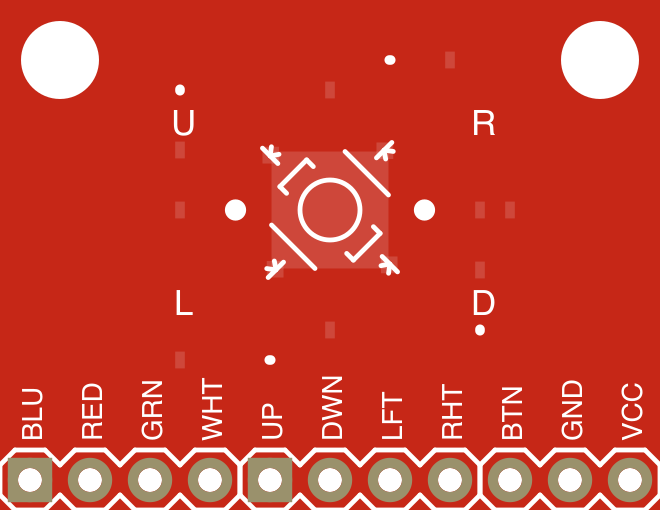
 Design with Blackberry Trackballer Breakout in Cirkit Designer
Introduction
The Blackberry Trackballer Breakout is a compact breakout board designed to interface with the trackball sensor commonly found in Blackberry devices. This module allows for seamless integration of the trackball into microcontroller-based projects, enabling precise directional input and button press detection. The breakout board simplifies the connection process by providing easy-to-use pins for power, ground, and signal outputs.
Explore Projects Built with Blackberry Trackballer Breakout
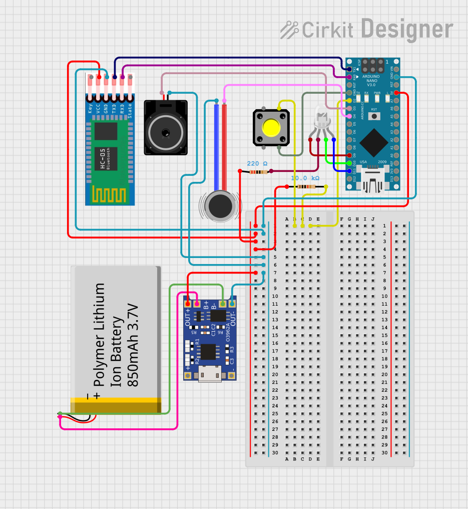 Open Project in Cirkit Designer
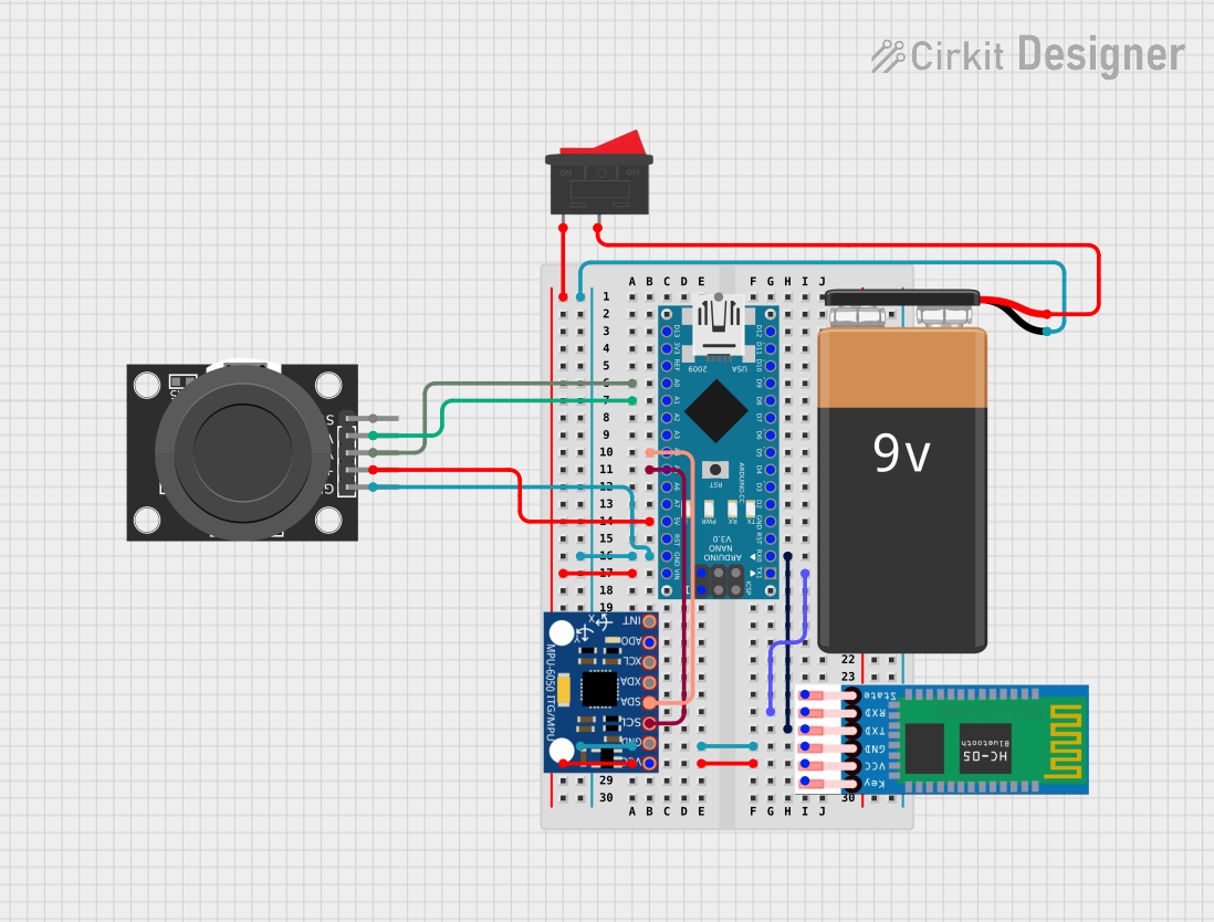 Open Project in Cirkit Designer
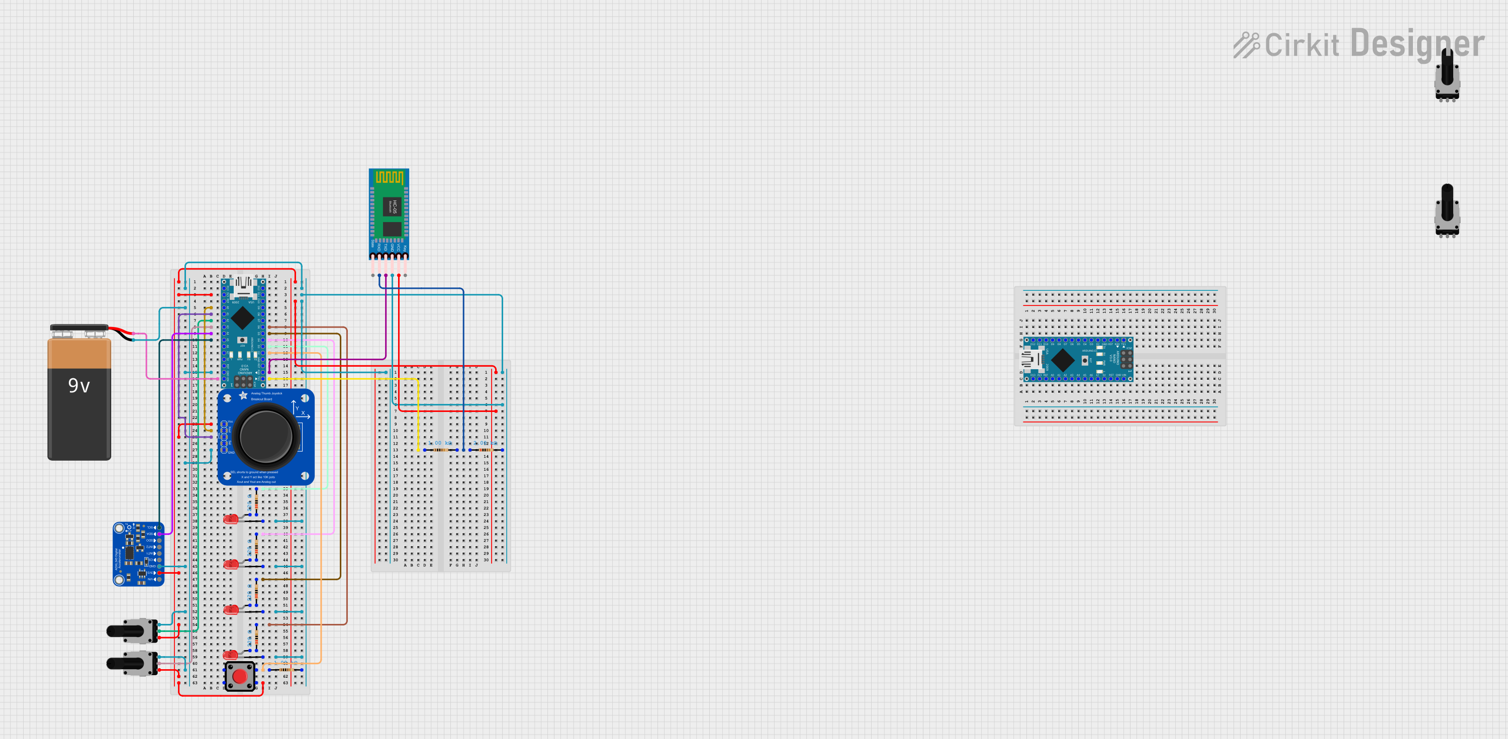 Open Project in Cirkit Designer
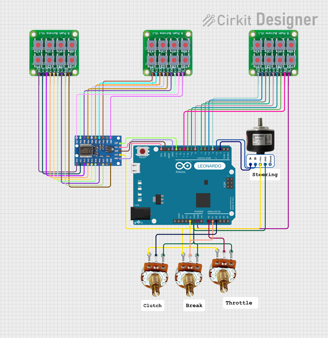 Open Project in Cirkit Designer
Explore Projects Built with Blackberry Trackballer Breakout
Open Project in Cirkit DesignerOpen Project in Cirkit DesignerOpen Project in Cirkit DesignerOpen Project in Cirkit DesignerCommon Applications and Use Cases
- Navigation controls for embedded systems
- User input for handheld devices
- Robotics and automation projects requiring directional control
- Custom game controllers
- Interactive art installations
Technical Specifications
The Blackberry Trackballer Breakout features a 4-directional trackball sensor with an integrated push-button. It uses optical encoders to detect movement in the X and Y axes and outputs signals via four quadrature pins. The breakout board is compatible with 3.3V and 5V logic levels, making it suitable for a wide range of microcontrollers.
Key Specifications
| Parameter | Value |
|---|---|
| Operating Voltage | 3.3V to 5V |
| Current Consumption | ~10mA |
| Output Type | Quadrature signals (X1, X2, Y1, Y2) |
| Push Button | Active-low signal |
| Dimensions | 25mm x 25mm |
Pin Configuration and Descriptions
| Pin Name | Description |
|---|---|
| VCC | Power supply input (3.3V to 5V). |
| GND | Ground connection. |
| X1 | Quadrature signal for X-axis movement (channel 1). |
| X2 | Quadrature signal for X-axis movement (channel 2). |
| Y1 | Quadrature signal for Y-axis movement (channel 1). |
| Y2 | Quadrature signal for Y-axis movement (channel 2). |
| SW | Push-button output (active-low). |
Usage Instructions
How to Use the Component in a Circuit
- Power the Module: Connect the
VCCpin to a 3.3V or 5V power source and theGNDpin to ground. - Connect Signal Pins:
- Connect
X1andX2to two digital input pins on your microcontroller to read X-axis movement. - Similarly, connect
Y1andY2to two digital input pins for Y-axis movement. - Connect the
SWpin to a digital input pin to detect button presses.
- Connect
- Read Quadrature Signals: Use the quadrature signals (
X1,X2,Y1,Y2) to determine the direction and speed of movement. The signals are phase-shifted to indicate direction. - Debounce the Button: If using the push-button, implement software or hardware debouncing to ensure reliable detection of button presses.
Important Considerations and Best Practices
- Pull-up Resistors: The
SWpin may require an external pull-up resistor if your microcontroller does not have internal pull-ups enabled. - Signal Decoding: Use a quadrature decoder library or write custom code to interpret the X and Y signals.
- Power Supply: Ensure the power supply voltage matches the operating voltage of the breakout board to avoid damage.
- Mechanical Mounting: Secure the breakout board to prevent unintended movement during operation.
Example Code for Arduino UNO
Below is an example of how to interface the Blackberry Trackballer Breakout with an Arduino UNO to read X and Y movements and detect button presses.
// Pin definitions
const int X1_PIN = 2;  // X1 signal connected to digital pin 2
const int X2_PIN = 3;  // X2 signal connected to digital pin 3
const int Y1_PIN = 4;  // Y1 signal connected to digital pin 4
const int Y2_PIN = 5;  // Y2 signal connected to digital pin 5
const int SW_PIN = 6;  // Push-button signal connected to digital pin 6

void setup() {
  // Configure pins as inputs
  pinMode(X1_PIN, INPUT);
  pinMode(X2_PIN, INPUT);
  pinMode(Y1_PIN, INPUT);
  pinMode(Y2_PIN, INPUT);
  pinMode(SW_PIN, INPUT_PULLUP); // Enable internal pull-up resistor for SW pin

  // Initialize serial communication for debugging
  Serial.begin(9600);
}

void loop() {
  // Read quadrature signals
  int x1 = digitalRead(X1_PIN);
  int x2 = digitalRead(X2_PIN);
  int y1 = digitalRead(Y1_PIN);
  int y2 = digitalRead(Y2_PIN);

  // Read button state
  int buttonState = digitalRead(SW_PIN);

  // Print the values to the Serial Monitor
  Serial.print("X1: "); Serial.print(x1);
  Serial.print(" X2: "); Serial.print(x2);
  Serial.print(" Y1: "); Serial.print(y1);
  Serial.print(" Y2: "); Serial.print(y2);
  Serial.print(" Button: "); Serial.println(buttonState == LOW ? "Pressed" : "Released");

  // Add a small delay to avoid flooding the Serial Monitor
  delay(100);
}
Troubleshooting and FAQs
Common Issues and Solutions
No Response from the Trackball:
- Ensure the
VCCandGNDpins are properly connected. - Verify that the power supply voltage is within the specified range (3.3V to 5V).
- Check for loose or incorrect wiring of the signal pins.
- Ensure the
Erratic or Incorrect Movement Detection:
- Ensure proper decoding of the quadrature signals (
X1,X2,Y1,Y2). - Check for electrical noise or interference on the signal lines.
- Use pull-up or pull-down resistors if necessary to stabilize the signals.
- Ensure proper decoding of the quadrature signals (
Button Not Detected:
- Verify that the
SWpin is connected to a digital input pin. - Ensure the pin is configured with a pull-up resistor (internal or external).
- Check for mechanical issues with the trackball's push-button.
- Verify that the
FAQs
Q: Can I use this breakout board with a 3.3V microcontroller?
A: Yes, the breakout board is compatible with both 3.3V and 5V logic levels.
Q: How do I decode the quadrature signals?
A: You can use a quadrature decoder library or write custom code to interpret the phase-shifted signals from X1, X2, Y1, and Y2.
Q: Is the push-button debounce necessary?
A: Yes, debouncing is recommended to ensure reliable detection of button presses, as mechanical switches can produce noise.
Q: Can I use this breakout board for gaming applications?
A: Absolutely! The trackball's precise directional input makes it suitable for custom game controllers and other interactive projects.