How to Use IRLB3034 MOSFET: Examples, Pinouts, and Specs
Introduction
The IRLB3034 is an N-channel MOSFET designed for high-speed switching applications. It features exceptionally low on-resistance (RDS(on)) and high current handling capabilities, making it ideal for power management, motor control, and other high-power applications. Its robust design ensures efficient operation in circuits requiring high current and low power loss.
Explore Projects Built with IRLB3034 MOSFET


Explore Projects Built with IRLB3034 MOSFET
Common Applications
- Motor drivers for robotics and industrial automation
- DC-DC converters and power supplies
- Battery management systems
- High-current switching circuits
- LED lighting control
Technical Specifications
Below are the key technical details of the IRLB3034 MOSFET:
| Parameter | Value |
|---|---|
| Type | N-Channel MOSFET |
| Maximum Drain-Source Voltage (VDS) | 40V |
| Maximum Gate-Source Voltage (VGS) | ±20V |
| Continuous Drain Current (ID) | 195A (at 25°C) |
| Pulsed Drain Current (IDM) | 780A |
| On-Resistance (RDS(on)) | 1.7mΩ (typical at VGS = 10V) |
| Total Gate Charge (Qg) | 170nC |
| Power Dissipation (PD) | 375W (at 25°C) |
| Operating Temperature Range | -55°C to +175°C |
| Package Type | TO-220AB |
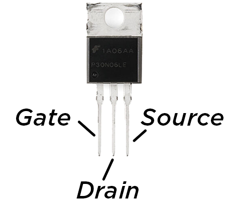
Pin Configuration
The IRLB3034 comes in a TO-220AB package with three pins. The pinout is as follows:
| Pin Number | Pin Name | Description |
|---|---|---|
| 1 | Gate (G) | Controls the MOSFET switching state |
| 2 | Drain (D) | Current flows into this terminal |
| 3 | Source (S) | Current flows out of this terminal |
Usage Instructions
How to Use the IRLB3034 in a Circuit
- Gate Control: Apply a voltage to the Gate (G) to control the MOSFET's switching state. A voltage of 10V or higher is recommended for full enhancement.
- Drain-Source Connection: Connect the load between the Drain (D) and the positive supply voltage. The Source (S) should be connected to ground.
- Gate Resistor: Use a resistor (typically 10Ω to 100Ω) between the Gate and the control signal to limit inrush current and prevent oscillations.
- Flyback Diode: For inductive loads (e.g., motors), add a flyback diode across the load to protect the MOSFET from voltage spikes.
Important Considerations
- Heat Dissipation: The IRLB3034 can handle high currents, but it generates heat. Use a heatsink or active cooling to prevent overheating.
- Gate Voltage: Ensure the Gate voltage does not exceed ±20V to avoid damaging the MOSFET.
- Switching Speed: Minimize parasitic inductance and capacitance in the circuit to achieve optimal switching performance.
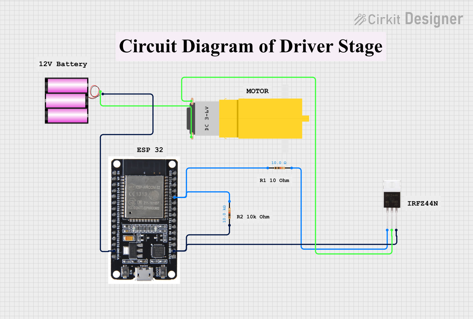
Example: Using IRLB3034 with Arduino UNO
Below is an example of controlling a DC motor using the IRLB3034 MOSFET and an Arduino UNO:
// Define the pin connected to the MOSFET Gate
const int mosfetGatePin = 9;

void setup() {
  // Set the MOSFET Gate pin as an output
  pinMode(mosfetGatePin, OUTPUT);
}

void loop() {
  // Turn the MOSFET on (motor runs)
  digitalWrite(mosfetGatePin, HIGH);
  delay(2000); // Keep the motor running for 2 seconds

  // Turn the MOSFET off (motor stops)
  digitalWrite(mosfetGatePin, LOW);
  delay(2000); // Wait for 2 seconds before restarting
}
Note:
- Use a 10kΩ pull-down resistor between the Gate and Source to ensure the MOSFET remains off when the Arduino pin is not actively driving it.
- Ensure the motor's current and voltage ratings are within the MOSFET's specifications.
Troubleshooting and FAQs
Common Issues
MOSFET Overheating
- Cause: Insufficient cooling or excessive current.
- Solution: Attach a heatsink or use active cooling. Ensure the current is within the MOSFET's rated limits.
MOSFET Not Switching
- Cause: Insufficient Gate voltage or incorrect wiring.
- Solution: Verify that the Gate voltage is at least 10V for full enhancement. Check the wiring and connections.
Voltage Spikes Damaging the MOSFET
- Cause: Inductive loads generating back EMF.
- Solution: Add a flyback diode across the load to suppress voltage spikes.
Low Switching Speed
- Cause: High parasitic capacitance or lack of a Gate resistor.
- Solution: Use a Gate resistor (10Ω to 100Ω) and minimize parasitic elements in the circuit.
FAQs
Q1: Can I use the IRLB3034 with a 3.3V logic level microcontroller?
A1: The IRLB3034 is not a logic-level MOSFET. It requires a Gate voltage of at least 10V for full enhancement. Use a level shifter or a logic-level MOSFET if working with 3.3V logic.
Q2: What is the maximum current the IRLB3034 can handle?
A2: The IRLB3034 can handle up to 195A continuously at 25°C, but this requires proper cooling. Without a heatsink, the current handling capability will be significantly lower.
Q3: Can I use the IRLB3034 for PWM applications?
A3: Yes, the IRLB3034 is suitable for PWM applications due to its low RDS(on) and fast switching characteristics. Ensure proper Gate drive circuitry for efficient operation.
Q4: How do I protect the IRLB3034 from damage?
A4: Use a flyback diode for inductive loads, a Gate resistor to limit inrush current, and a heatsink to manage heat dissipation. Avoid exceeding the voltage and current ratings.