How to Use Cytron: Examples, Pinouts, and Specs
Introduction
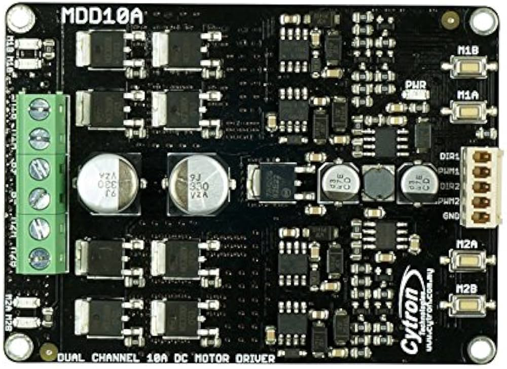
The Cytron MDD10A is a robust dual-channel motor driver designed for high-power DC motor control. Manufactured by Arduino, this motor driver is capable of driving two brushed DC motors with a continuous current of up to 10A per channel. It features a wide operating voltage range and supports both PWM and direction control, making it ideal for robotics, automation, and other motor control applications.
Explore Projects Built with Cytron

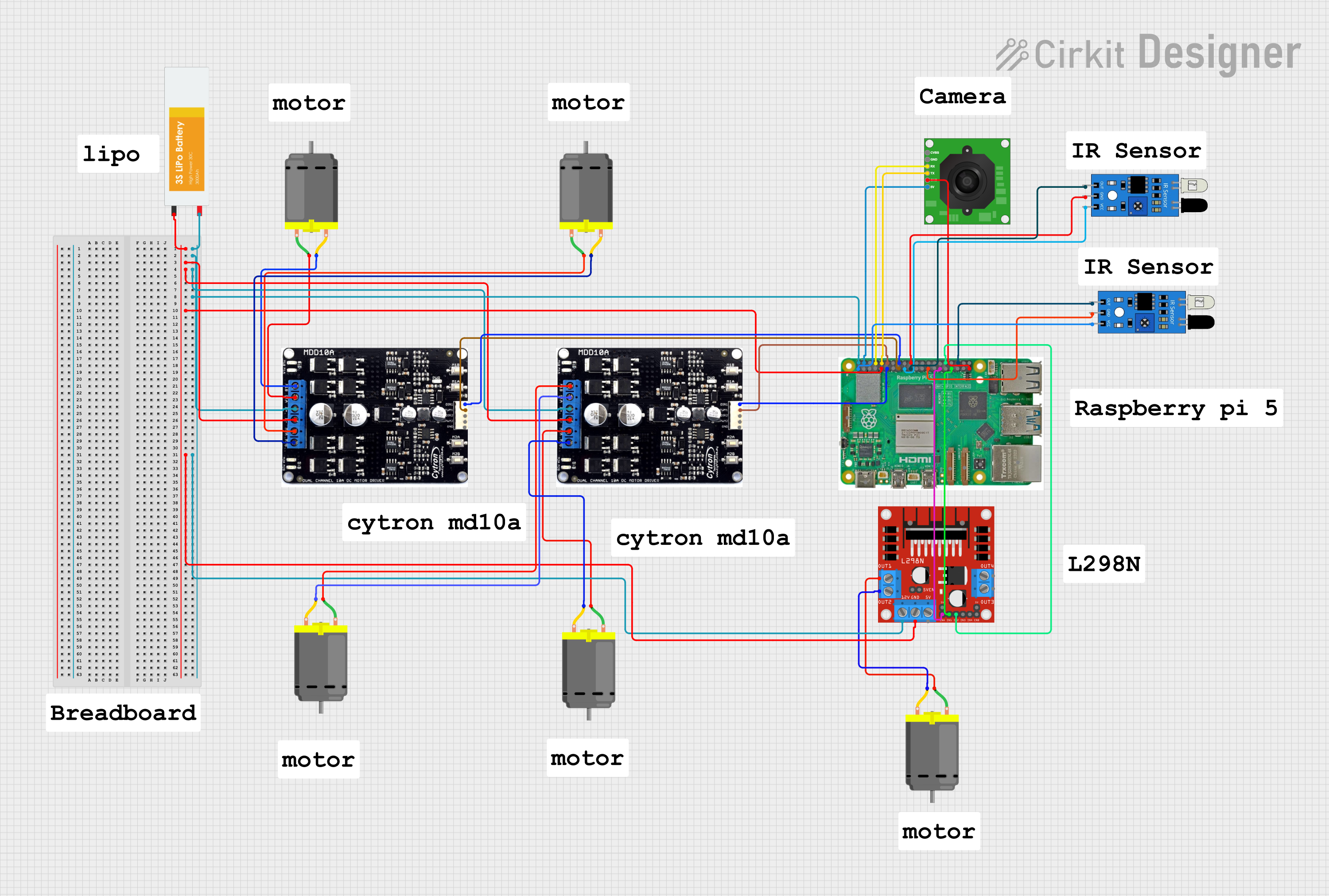
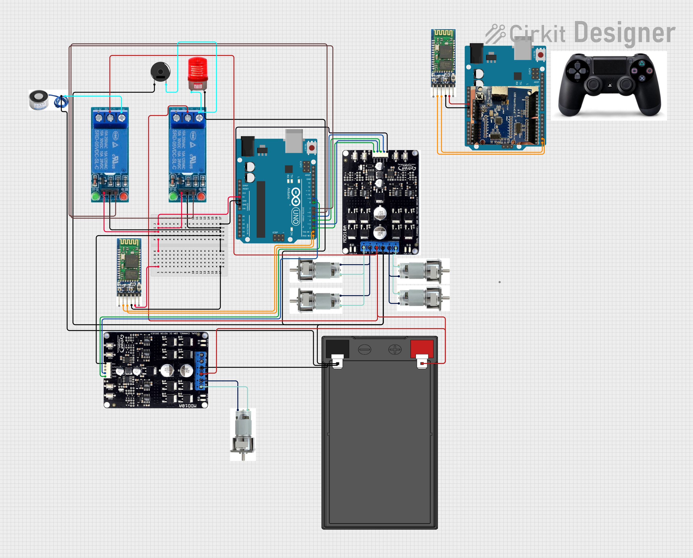
Explore Projects Built with Cytron
Common Applications and Use Cases
- Robotics projects requiring precise motor control
- Automated guided vehicles (AGVs)
- Conveyor belt systems
- Remote-controlled vehicles
- Industrial automation systems
Technical Specifications
The Cytron MDD10A is designed to handle high-power motor control with ease. Below are its key technical specifications:
| Parameter | Specification |
|---|---|
| Operating Voltage | 7V to 30V DC |
| Continuous Current | 10A per channel |
| Peak Current | 30A per channel (for 10 seconds) |
| Control Interface | PWM and Direction |
| PWM Frequency | Up to 20 kHz |
| Logic Voltage | 3.3V or 5V (compatible with Arduino) |
| Protection Features | Overcurrent, Overtemperature, Reverse Polarity |
| Dimensions | 84mm x 62mm x 25mm |
| Weight | 80g |
Pin Configuration and Descriptions
The Cytron MDD10A has a straightforward pin layout for easy integration into your projects. Below is the pin configuration:
| Pin Name | Type | Description |
|---|---|---|
| VM | Power Input | Motor power supply (7V to 30V DC). |
| GND | Power Ground | Ground connection for the motor power supply. |
| DIR1 | Input | Direction control for Motor 1. |
| PWM1 | Input | PWM signal for Motor 1 speed control. |
| DIR2 | Input | Direction control for Motor 2. |
| PWM2 | Input | PWM signal for Motor 2 speed control. |
| M1A | Output | Motor 1 terminal A. |
| M1B | Output | Motor 1 terminal B. |
| M2A | Output | Motor 2 terminal A. |
| M2B | Output | Motor 2 terminal B. |
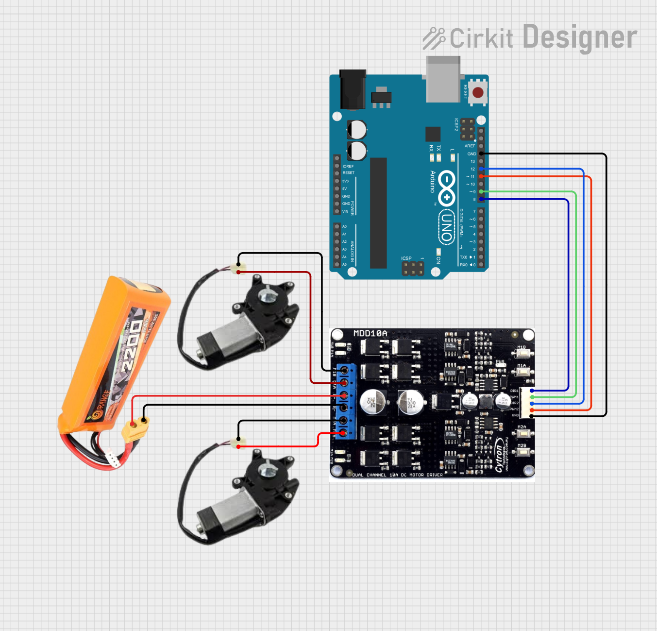
Usage Instructions
How to Use the Cytron MDD10A in a Circuit
- Power Supply: Connect the motor power supply (7V to 30V DC) to the
VMpin and the ground to theGNDpin. - Motor Connections: Connect the terminals of Motor 1 to
M1AandM1B, and Motor 2 toM2AandM2B. - Control Signals:
- Connect the
DIR1andPWM1pins to your microcontroller for Motor 1 control. - Similarly, connect the
DIR2andPWM2pins for Motor 2 control.
- Connect the
- Logic Voltage Compatibility: Ensure the control signals are compatible with the motor driver (3.3V or 5V logic).
- PWM Frequency: Set the PWM frequency on your microcontroller to a value up to 20 kHz for smooth motor operation.
Important Considerations and Best Practices
- Heat Dissipation: The MDD10A can handle high currents, but ensure proper ventilation or use a heatsink if operating near the maximum current for extended periods.
- Reverse Polarity Protection: The driver includes reverse polarity protection, but double-check your connections to avoid damage.
- PWM Signal Quality: Use a clean PWM signal to avoid erratic motor behavior.
- Motor Voltage: Ensure the motor voltage matches the power supply voltage to prevent damage to the motors or the driver.
Example Code for Arduino UNO
Below is an example code snippet to control two DC motors using the Cytron MDD10A with an Arduino UNO:
// Define motor control pins
const int DIR1 = 7;  // Direction pin for Motor 1
const int PWM1 = 6;  // PWM pin for Motor 1
const int DIR2 = 4;  // Direction pin for Motor 2
const int PWM2 = 5;  // PWM pin for Motor 2

void setup() {
  // Set motor control pins as outputs
  pinMode(DIR1, OUTPUT);
  pinMode(PWM1, OUTPUT);
  pinMode(DIR2, OUTPUT);
  pinMode(PWM2, OUTPUT);
}

void loop() {
  // Motor 1: Forward at 50% speed
  digitalWrite(DIR1, HIGH);  // Set direction forward
  analogWrite(PWM1, 128);    // Set speed (0-255)

  // Motor 2: Reverse at 75% speed
  digitalWrite(DIR2, LOW);   // Set direction reverse
  analogWrite(PWM2, 192);    // Set speed (0-255)

  delay(2000);  // Run motors for 2 seconds

  // Stop both motors
  analogWrite(PWM1, 0);
  analogWrite(PWM2, 0);

  delay(2000);  // Wait for 2 seconds
}
Troubleshooting and FAQs
Common Issues and Solutions
Motors Not Running:
- Check the power supply voltage and ensure it is within the 7V to 30V range.
- Verify the control signal connections (
DIRandPWM) to the microcontroller. - Ensure the motor connections (
M1A,M1B,M2A,M2B) are secure.
Erratic Motor Behavior:
- Ensure the PWM frequency is set correctly (up to 20 kHz).
- Check for noise or interference in the control signals.
Overheating:
- Reduce the motor load or provide additional cooling to the driver.
- Ensure the current does not exceed 10A per channel continuously.
No Response from the Driver:
- Verify the logic voltage level (3.3V or 5V) matches the microcontroller output.
- Check for reverse polarity or short circuits in the connections.
FAQs
Q: Can I use the MDD10A with a 3.3V microcontroller?
A: Yes, the MDD10A is compatible with both 3.3V and 5V logic levels.
Q: What happens if the current exceeds 10A per channel?
A: The driver includes overcurrent protection, but prolonged overcurrent may trigger thermal shutdown or damage the driver.
Q: Can I control the speed and direction of two motors independently?
A: Yes, the MDD10A allows independent control of speed and direction for two motors using separate DIR and PWM pins.
Q: Is the MDD10A suitable for battery-powered applications?
A: Yes, the wide voltage range (7V to 30V) makes it suitable for battery-powered systems. Ensure the battery can supply sufficient current for the motors.