
How to Use Push Button Switch: Examples, Pinouts, and Specs

 Design with Push Button Switch in Cirkit Designer
Introduction
A push button switch is a momentary switch that completes an electrical circuit when pressed and breaks the circuit when released. It is widely used in electronic devices for user input, such as turning devices on/off, resetting systems, or triggering specific actions. Its simple design and functionality make it a fundamental component in both hobbyist and professional electronics projects.
Explore Projects Built with Push Button Switch
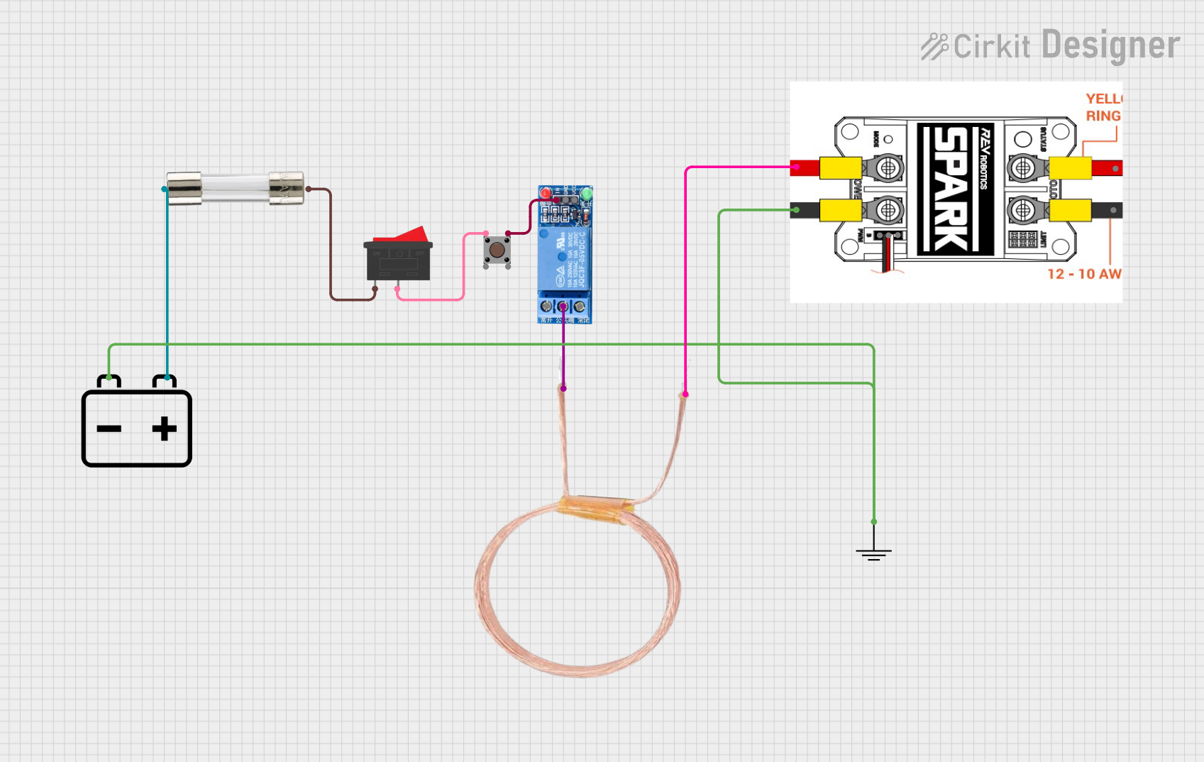 Open Project in Cirkit Designer
 Open Project in Cirkit Designer
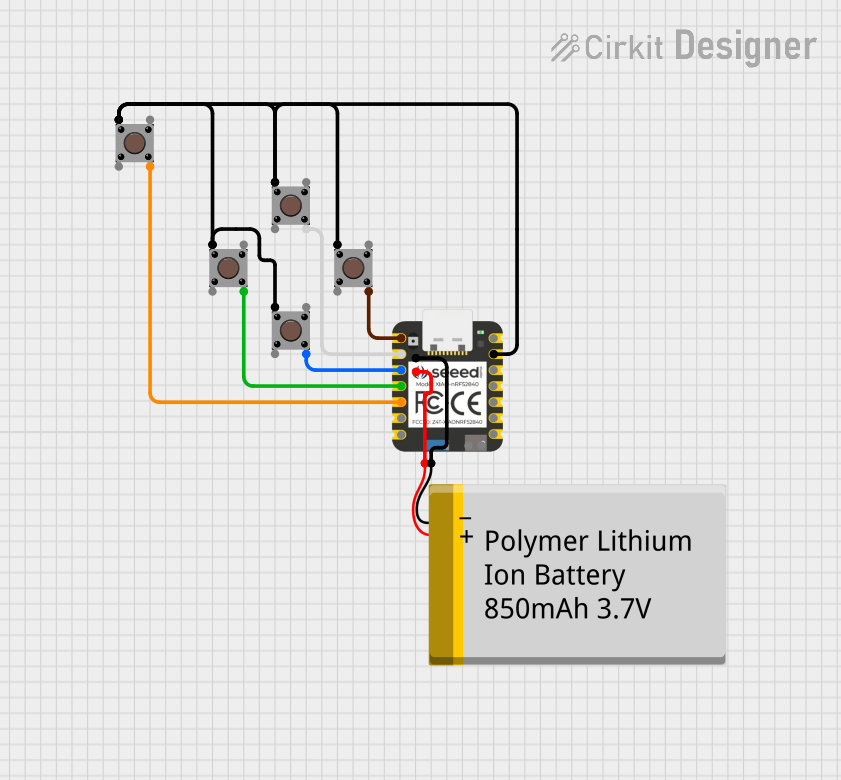 Open Project in Cirkit Designer
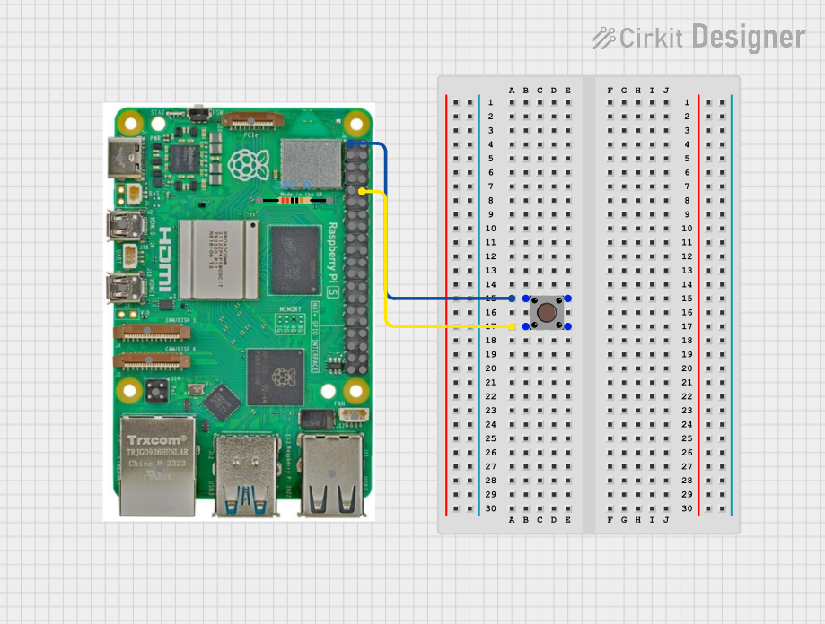 Open Project in Cirkit Designer
Explore Projects Built with Push Button Switch
Open Project in Cirkit DesignerOpen Project in Cirkit DesignerOpen Project in Cirkit DesignerOpen Project in Cirkit DesignerCommon Applications and Use Cases
- Power buttons for electronic devices
- Reset switches in microcontroller circuits
- User input for embedded systems
- Triggering events in Arduino or Raspberry Pi projects
- Control panels for appliances and machinery
Technical Specifications
Below are the general technical specifications for a standard push button switch. Note that specific values may vary depending on the manufacturer and model.
| Parameter | Specification |
|---|---|
| Type | Momentary (Normally Open or Closed) |
| Operating Voltage | 3V to 24V DC |
| Operating Current | 10mA to 50mA (typical) |
| Contact Resistance | ≤ 50 mΩ |
| Insulation Resistance | ≥ 100 MΩ |
| Mechanical Life | 100,000 to 1,000,000 cycles |
| Operating Temperature | -20°C to +70°C |
Pin Configuration and Descriptions
A standard push button switch typically has two or four pins. The table below describes the pin configuration:
| Pin Number | Description |
|---|---|
| 1 | Terminal 1 of the switch |
| 2 | Terminal 2 of the switch |
| 3 (optional) | Terminal 3 (used in DPST or DPDT switches) |
| 4 (optional) | Terminal 4 (used in DPST or DPDT switches) |
For a basic momentary push button, only two pins are used. When the button is pressed, the two pins are electrically connected.
Usage Instructions
How to Use the Push Button Switch in a Circuit
- Identify the Pins: For a basic push button, locate the two pins that will be connected when the button is pressed.
- Connect to Circuit:
- Connect one pin to the input signal or power source.
- Connect the other pin to the load or microcontroller input pin.
- Debounce the Signal: Push buttons can produce noise or "bouncing" when pressed. Use a capacitor (e.g., 0.1 µF) or software debounce techniques to stabilize the signal.
- Test the Circuit: Verify that the button completes the circuit when pressed and breaks it when released.
Important Considerations and Best Practices
- Voltage and Current Ratings: Ensure the button's voltage and current ratings match your circuit requirements.
- Debouncing: Always account for signal bouncing to avoid erratic behavior in your circuit.
- Mounting: Secure the button properly to prevent mechanical stress or accidental disconnection.
- Polarity: Push buttons are generally non-polarized, so pin orientation does not matter.
Example: Using a Push Button with Arduino UNO
Below is an example of how to use a push button switch with an Arduino UNO to toggle an LED:
// Define pin numbers
const int buttonPin = 2;  // Push button connected to digital pin 2
const int ledPin = 13;    // LED connected to digital pin 13

// Variable to store button state
int buttonState = 0;

void setup() {
  pinMode(buttonPin, INPUT);  // Set button pin as input
  pinMode(ledPin, OUTPUT);   // Set LED pin as output
}

void loop() {
  // Read the state of the push button
  buttonState = digitalRead(buttonPin);

  // If button is pressed, turn on the LED
  if (buttonState == HIGH) {
    digitalWrite(ledPin, HIGH);  // Turn LED on
  } else {
    digitalWrite(ledPin, LOW);   // Turn LED off
  }
}
Note: Use a pull-down resistor (e.g., 10 kΩ) between the button pin and ground to ensure a stable LOW state when the button is not pressed.
Troubleshooting and FAQs
Common Issues and Solutions
Button Not Responding:
- Check the wiring and ensure the button is properly connected.
- Verify that the button is not damaged or worn out.
- Ensure the voltage and current ratings are within the button's specifications.
Erratic Behavior (Button Bouncing):
- Add a capacitor (e.g., 0.1 µF) across the button terminals to reduce noise.
- Implement software debouncing in your microcontroller code.
LED or Load Not Turning On:
- Verify the polarity and connections of the LED or load.
- Check the power supply and ensure it is functioning correctly.
FAQs
Q: Can I use a push button switch for AC circuits?
A: Yes, but ensure the switch is rated for the AC voltage and current you plan to use.
Q: What is the difference between a momentary and a latching switch?
A: A momentary switch only stays in its active state while pressed, whereas a latching switch maintains its state until pressed again.
Q: How do I debounce a push button in software?
A: Use a delay or a state-checking algorithm in your code to filter out rapid changes in the button state caused by bouncing.
Q: Can I use a push button switch with a Raspberry Pi?
A: Yes, connect the button to a GPIO pin and use a pull-up or pull-down resistor to stabilize the signal.
This concludes the documentation for the push button switch.