Cirkit Designer Logo
Cirkit Designer
Your all-in-one circuit design IDE
Home / 
Component Documentation

How to Use GUVA S12SD: Examples, Pinouts, and Specs

Image of GUVA S12SD
Cirkit Designer LogoDesign with GUVA S12SD in Cirkit Designer

Introduction

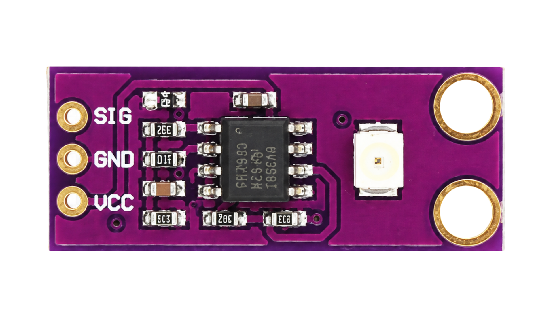
The GUVA S12SD is a UV light sensor designed to detect ultraviolet (UV) radiation. It provides an analog output voltage that is directly proportional to the intensity of UV light, making it an ideal choice for applications requiring accurate UV detection. This sensor is compact, reliable, and easy to integrate into various systems.

Explore Projects Built with GUVA S12SD

Use Cirkit Designer to design, explore, and prototype these projects online. Some projects support real-time simulation. Click "Open Project" to start designing instantly!
ESP32-S3 Based Vibration Detection System with TFT Display and Power Backup
Image of IOT Thesis: A project utilizing GUVA S12SD in a practical application
This circuit features an ESP32-S3 microcontroller connected to various peripherals including an ADXL355 accelerometer, an SW-420 vibration sensor, a buzzer module, and an ILI9341 TFT display. The ESP32-S3 manages sensor inputs and provides output to the display and buzzer. Power management is handled by a 12V to 5V step-down converter, and a UPS ensures uninterrupted power supply, with a rocker switch to control the power flow.
Cirkit Designer LogoOpen Project in Cirkit Designer
Cellular-Enabled IoT Device with Real-Time Clock and Power Management
Image of LRCM PHASE 2 BASIC: A project utilizing GUVA S12SD in a practical application
This circuit features a LilyGo-SIM7000G module for cellular communication and GPS functionality, interfaced with an RTC DS3231 for real-time clock capabilities. It includes voltage sensing through two voltage sensor modules, and uses an 8-channel opto-coupler for isolating different parts of the circuit. Power management is handled by a buck converter connected to a DC power source and batteries, with a fuse for protection and a rocker switch for on/off control. Additionally, there's an LED for indication purposes.
Cirkit Designer LogoOpen Project in Cirkit Designer
ESP32-S3 GPS and Wind Speed Logger with Dual OLED Displays and CAN Bus
Image of esp32-s3-ellipse: A project utilizing GUVA S12SD in a practical application
This circuit features an ESP32-S3 microcontroller interfaced with an SD card module, two OLED displays, a GPS module, and a CAN bus module. The ESP32-S3 records GPS data to the SD card, displays speed on one OLED, and shows wind speed from the CAN bus on the other OLED, providing a comprehensive data logging and display system.
Cirkit Designer LogoOpen Project in Cirkit Designer
ESP32-S3 Battery-Powered Environmental Monitoring System with OLED Display
Image of Diagram wiring: A project utilizing GUVA S12SD in a practical application
This circuit is a sensor and display system powered by a UPS module with a 12V power supply and 18650 batteries. It includes an ESP32 microcontroller that interfaces with various sensors (DHT22, Strain Gauge, MPU-6050, ADXL345) and an OLED display, with power regulation provided by a step-down buck converter.
Cirkit Designer LogoOpen Project in Cirkit Designer

Explore Projects Built with GUVA S12SD

Use Cirkit Designer to design, explore, and prototype these projects online. Some projects support real-time simulation. Click "Open Project" to start designing instantly!
Image of IOT Thesis: A project utilizing GUVA S12SD in a practical application
ESP32-S3 Based Vibration Detection System with TFT Display and Power Backup
This circuit features an ESP32-S3 microcontroller connected to various peripherals including an ADXL355 accelerometer, an SW-420 vibration sensor, a buzzer module, and an ILI9341 TFT display. The ESP32-S3 manages sensor inputs and provides output to the display and buzzer. Power management is handled by a 12V to 5V step-down converter, and a UPS ensures uninterrupted power supply, with a rocker switch to control the power flow.
Cirkit Designer LogoOpen Project in Cirkit Designer
Image of LRCM PHASE 2 BASIC: A project utilizing GUVA S12SD in a practical application
Cellular-Enabled IoT Device with Real-Time Clock and Power Management
This circuit features a LilyGo-SIM7000G module for cellular communication and GPS functionality, interfaced with an RTC DS3231 for real-time clock capabilities. It includes voltage sensing through two voltage sensor modules, and uses an 8-channel opto-coupler for isolating different parts of the circuit. Power management is handled by a buck converter connected to a DC power source and batteries, with a fuse for protection and a rocker switch for on/off control. Additionally, there's an LED for indication purposes.
Cirkit Designer LogoOpen Project in Cirkit Designer
Image of esp32-s3-ellipse: A project utilizing GUVA S12SD in a practical application
ESP32-S3 GPS and Wind Speed Logger with Dual OLED Displays and CAN Bus
This circuit features an ESP32-S3 microcontroller interfaced with an SD card module, two OLED displays, a GPS module, and a CAN bus module. The ESP32-S3 records GPS data to the SD card, displays speed on one OLED, and shows wind speed from the CAN bus on the other OLED, providing a comprehensive data logging and display system.
Cirkit Designer LogoOpen Project in Cirkit Designer
Image of Diagram wiring: A project utilizing GUVA S12SD in a practical application
ESP32-S3 Battery-Powered Environmental Monitoring System with OLED Display
This circuit is a sensor and display system powered by a UPS module with a 12V power supply and 18650 batteries. It includes an ESP32 microcontroller that interfaces with various sensors (DHT22, Strain Gauge, MPU-6050, ADXL345) and an OLED display, with power regulation provided by a step-down buck converter.
Cirkit Designer LogoOpen Project in Cirkit Designer

Common Applications and Use Cases

  • Environmental monitoring systems
  • UV exposure measurement devices
  • Safety systems for UV radiation detection
  • Wearable UV monitoring devices
  • UV index measurement in weather stations

Technical Specifications

The following table outlines the key technical details of the GUVA S12SD UV sensor:

Parameter Value
Manufacturer UNKNOWN
Manufacturer Part ID SENSOR UV
Operating Voltage (Vcc) 3.3V to 5V
Output Voltage Range 0V to Vcc
Spectral Response Range 200 nm to 370 nm
Peak Sensitivity Wavelength 365 nm
Operating Temperature -30°C to +85°C
Dimensions 10 mm x 10 mm x 1.2 mm

Pin Configuration and Descriptions

The GUVA S12SD has three pins, as described in the table below:

Pin Name Description
1 VCC Power supply input (3.3V to 5V)
2 GND Ground connection
3 OUT Analog output voltage proportional to UV intensity

Usage Instructions

How to Use the GUVA S12SD in a Circuit

  1. Power Supply: Connect the VCC pin to a 3.3V or 5V power source and the GND pin to the ground of your circuit.
  2. Analog Output: Connect the OUT pin to an analog input pin of a microcontroller (e.g., Arduino UNO) or an analog-to-digital converter (ADC) to read the sensor's output voltage.
  3. UV Intensity Measurement: The output voltage from the OUT pin is proportional to the UV light intensity. Use the sensor's datasheet or calibration data to convert the voltage into UV index or intensity values.

Important Considerations and Best Practices

  • Avoid Overexposure: Prolonged exposure to high-intensity UV light may degrade the sensor's performance over time.
  • Calibration: For accurate measurements, calibrate the sensor using a known UV light source.
  • Noise Reduction: Use a capacitor (e.g., 0.1 µF) between VCC and GND to reduce power supply noise.
  • Placement: Ensure the sensor is placed in a location with a clear line of sight to the UV source for optimal performance.

Example: Connecting GUVA S12SD to an Arduino UNO

Below is an example of how to connect and read data from the GUVA S12SD using an Arduino UNO:

Circuit Connections

  • Connect the VCC pin of the GUVA S12SD to the 5V pin of the Arduino.
  • Connect the GND pin of the GUVA S12SD to the GND pin of the Arduino.
  • Connect the OUT pin of the GUVA S12SD to the A0 analog input pin of the Arduino.

Arduino Code

// GUVA S12SD UV Sensor Example Code
// Reads the analog output from the sensor and prints the UV intensity to the Serial Monitor.

const int uvSensorPin = A0; // Analog pin connected to the sensor's OUT pin

void setup() {
  Serial.begin(9600); // Initialize serial communication at 9600 baud
}

void loop() {
  int sensorValue = analogRead(uvSensorPin); // Read the analog value from the sensor
  float voltage = sensorValue * (5.0 / 1023.0); // Convert the analog value to voltage
  
  // Print the sensor value and voltage to the Serial Monitor
  Serial.print("Sensor Value: ");
  Serial.print(sensorValue);
  Serial.print(" | Voltage: ");
  Serial.print(voltage);
  Serial.println(" V");
  
  delay(1000); // Wait for 1 second before the next reading
}

Troubleshooting and FAQs

Common Issues and Solutions

  1. No Output Voltage:

    • Cause: Incorrect wiring or insufficient power supply.
    • Solution: Verify all connections and ensure the VCC pin is supplied with 3.3V to 5V.
  2. Fluctuating Output:

    • Cause: Electrical noise or unstable power supply.
    • Solution: Add a decoupling capacitor (e.g., 0.1 µF) between VCC and GND to stabilize the power supply.
  3. Low Sensitivity:

    • Cause: Sensor placement or degradation due to prolonged UV exposure.
    • Solution: Ensure the sensor has a clear line of sight to the UV source and replace the sensor if necessary.
  4. Incorrect Readings:

    • Cause: Lack of calibration or incorrect conversion of voltage to UV intensity.
    • Solution: Calibrate the sensor using a known UV light source and verify the conversion formula.

FAQs

Q: Can the GUVA S12SD detect visible light?
A: No, the GUVA S12SD is specifically designed to detect UV light in the 200 nm to 370 nm range and is not sensitive to visible light.

Q: Is the sensor waterproof?
A: No, the GUVA S12SD is not waterproof. Protect it from moisture and water exposure during use.

Q: Can I use the sensor with a 3.3V microcontroller?
A: Yes, the GUVA S12SD operates with a supply voltage range of 3.3V to 5V, making it compatible with 3.3V microcontrollers.

Q: How do I convert the output voltage to a UV index?
A: Refer to the sensor's datasheet or calibration data to determine the relationship between output voltage and UV index. Calibration with a known UV source is recommended for accurate results.