Cirkit Designer Logo
Cirkit Designer
Your all-in-one circuit design IDE
Home / 
Component Documentation

How to Use MAX4080: Examples, Pinouts, and Specs

Image of MAX4080
Cirkit Designer LogoDesign with MAX4080 in Cirkit Designer

Introduction

The MAX4080 is a high-speed, precision current-sense amplifier designed for both low-side and high-side current sensing applications. It is engineered to provide accurate current measurements in a variety of systems, thanks to its wide supply voltage range, low offset voltage, and high common-mode rejection ratio (CMRR). These features make the MAX4080 an ideal choice for applications such as battery management systems, motor control, power monitoring, and industrial automation.

Explore Projects Built with MAX4080

Use Cirkit Designer to design, explore, and prototype these projects online. Some projects support real-time simulation. Click "Open Project" to start designing instantly!
Battery-Powered Health Monitoring System with Nucleo WB55RG and OLED Display
Image of Pulsefex: A project utilizing MAX4080 in a practical application
This circuit is a multi-sensor data acquisition system that uses a Nucleo WB55RG microcontroller to interface with a digital temperature sensor (TMP102), a pulse oximeter and heart-rate sensor (MAX30102), and a 0.96" OLED display via I2C. Additionally, it includes a Sim800l module for GSM communication, powered by a 3.7V LiPo battery.
Cirkit Designer LogoOpen Project in Cirkit Designer
ESP32-Based Multi-Sensor Health Monitoring System with Bluetooth Connectivity
Image of circuit diagram: A project utilizing MAX4080 in a practical application
This circuit features an ESP32-WROOM-32UE microcontroller as the central processing unit, interfacing with a variety of sensors and modules. It includes a MAX30100 pulse oximeter and heart-rate sensor, an MLX90614 infrared thermometer, an HC-05 Bluetooth module for wireless communication, and a Neo 6M GPS module for location tracking. All components are powered by a common voltage supply and are connected to specific GPIO pins on the ESP32 for data exchange, with the sensors using I2C communication and the modules using UART.
Cirkit Designer LogoOpen Project in Cirkit Designer
ESP32-Based Health Monitoring System with MAX30102 and MAX30205 Sensors
Image of capstone: A project utilizing MAX4080 in a practical application
This circuit features an ESP32 microcontroller as the central processing unit, interfacing with a MAX30102 pulse oximeter sensor and a MAX30205 temperature sensor via I2C communication (using GPIOs 21 and 22 for SDA and SCL, respectively). Additionally, it includes a Sim A7670c module for cellular connectivity (connected to GPIOs 16 and 17 for UART communication), and a 0.96" OLED display for data output, also on the I2C bus. All components share a common ground and are powered by a 5V supply connected to the ESP32.
Cirkit Designer LogoOpen Project in Cirkit Designer
ESP32-Based Environmental Monitoring System with Solar Charging
Image of IoT Ola (Final): A project utilizing MAX4080 in a practical application
This circuit features an ESP32 microcontroller interfaced with a BME/BMP280 sensor for environmental monitoring and an MH-Z19B sensor for CO2 measurement, both communicating via I2C (SCL, SDA) and serial (TX, RX) connections respectively. It includes a SIM800L module for GSM communication, connected to the ESP32 via serial (TXD, RXD). Power management is handled by two TP4056 modules for charging 18650 Li-ion batteries via solar panels, with a step-up boost converter to provide consistent voltage to the MH-Z19B, and voltage regulation for the SIM800L. Decoupling capacitors are used to stabilize the power supply to the BME/BMP280 and ESP32.
Cirkit Designer LogoOpen Project in Cirkit Designer

Explore Projects Built with MAX4080

Use Cirkit Designer to design, explore, and prototype these projects online. Some projects support real-time simulation. Click "Open Project" to start designing instantly!
Image of Pulsefex: A project utilizing MAX4080 in a practical application
Battery-Powered Health Monitoring System with Nucleo WB55RG and OLED Display
This circuit is a multi-sensor data acquisition system that uses a Nucleo WB55RG microcontroller to interface with a digital temperature sensor (TMP102), a pulse oximeter and heart-rate sensor (MAX30102), and a 0.96" OLED display via I2C. Additionally, it includes a Sim800l module for GSM communication, powered by a 3.7V LiPo battery.
Cirkit Designer LogoOpen Project in Cirkit Designer
Image of circuit diagram: A project utilizing MAX4080 in a practical application
ESP32-Based Multi-Sensor Health Monitoring System with Bluetooth Connectivity
This circuit features an ESP32-WROOM-32UE microcontroller as the central processing unit, interfacing with a variety of sensors and modules. It includes a MAX30100 pulse oximeter and heart-rate sensor, an MLX90614 infrared thermometer, an HC-05 Bluetooth module for wireless communication, and a Neo 6M GPS module for location tracking. All components are powered by a common voltage supply and are connected to specific GPIO pins on the ESP32 for data exchange, with the sensors using I2C communication and the modules using UART.
Cirkit Designer LogoOpen Project in Cirkit Designer
Image of capstone: A project utilizing MAX4080 in a practical application
ESP32-Based Health Monitoring System with MAX30102 and MAX30205 Sensors
This circuit features an ESP32 microcontroller as the central processing unit, interfacing with a MAX30102 pulse oximeter sensor and a MAX30205 temperature sensor via I2C communication (using GPIOs 21 and 22 for SDA and SCL, respectively). Additionally, it includes a Sim A7670c module for cellular connectivity (connected to GPIOs 16 and 17 for UART communication), and a 0.96" OLED display for data output, also on the I2C bus. All components share a common ground and are powered by a 5V supply connected to the ESP32.
Cirkit Designer LogoOpen Project in Cirkit Designer
Image of IoT Ola (Final): A project utilizing MAX4080 in a practical application
ESP32-Based Environmental Monitoring System with Solar Charging
This circuit features an ESP32 microcontroller interfaced with a BME/BMP280 sensor for environmental monitoring and an MH-Z19B sensor for CO2 measurement, both communicating via I2C (SCL, SDA) and serial (TX, RX) connections respectively. It includes a SIM800L module for GSM communication, connected to the ESP32 via serial (TXD, RXD). Power management is handled by two TP4056 modules for charging 18650 Li-ion batteries via solar panels, with a step-up boost converter to provide consistent voltage to the MH-Z19B, and voltage regulation for the SIM800L. Decoupling capacitors are used to stabilize the power supply to the BME/BMP280 and ESP32.
Cirkit Designer LogoOpen Project in Cirkit Designer

Common Applications:

  • Battery management systems (BMS)
  • Motor control and protection circuits
  • Power supply monitoring
  • Industrial automation and control systems
  • Overcurrent protection circuits

Technical Specifications

Key Technical Details:

  • Supply Voltage (Vcc): 4.5V to 76V
  • Input Common-Mode Voltage Range: 0V to 76V
  • Gain Options: Fixed gains of 5V/V, 20V/V, 60V/V (depending on the model)
  • Output Voltage Range: 0V to (Vcc - 0.25V)
  • Bandwidth: 200kHz (typical)
  • Offset Voltage: ±0.1mV (typical)
  • Operating Temperature Range: -40°C to +125°C
  • Package Options: 8-pin SOIC (Small Outline Integrated Circuit)

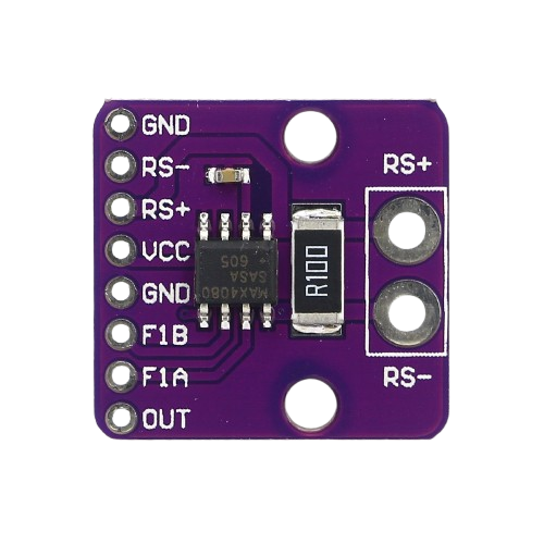
Pin Configuration and Descriptions:

The MAX4080 is available in an 8-pin SOIC package. Below is the pinout and description:

Pin Number Pin Name Description
1 VCC Power supply input (4.5V to 76V).
2 OUT Output voltage proportional to the sensed current.
3 GND Ground connection.
4 REF Reference voltage input. Sets the output voltage when no current is sensed.
5 RS+ Positive input for the current-sense resistor.
6 RS- Negative input for the current-sense resistor.
7 NC No connection. Leave unconnected or grounded.
8 NC No connection. Leave unconnected or grounded.

Usage Instructions

How to Use the MAX4080 in a Circuit:

  1. Power Supply: Connect the VCC pin to a power supply voltage between 4.5V and 76V. Ensure proper decoupling with a bypass capacitor (e.g., 0.1µF) close to the VCC pin.
  2. Current-Sense Resistor (Rs): Place a low-value resistor (e.g., 10mΩ to 100mΩ) in series with the load to measure current. Connect the RS+ and RS- pins across this resistor.
  3. Reference Voltage (REF): Apply a reference voltage to the REF pin. For single-supply operation, this is typically connected to ground or a mid-supply voltage.
  4. Output Voltage (OUT): The output voltage is proportional to the current flowing through the sense resistor. Use the formula: [ V_{OUT} = (I_{LOAD} \times R_S) \times \text{Gain} + V_{REF} ] where ( I_{LOAD} ) is the load current, ( R_S ) is the sense resistor value, and Gain is the fixed gain of the MAX4080 (5V/V, 20V/V, or 60V/V).
  5. Load Connection: Connect the load in series with the current-sense resistor.

Important Considerations:

  • Sense Resistor Selection: Choose a resistor with low inductance and sufficient power rating to handle the expected current.
  • PCB Layout: Minimize trace resistance and ensure proper grounding to reduce noise and improve accuracy.
  • Input Voltage Range: Ensure the common-mode voltage at RS+ and RS- does not exceed the specified range (0V to 76V).
  • Output Loading: Avoid heavy loading on the OUT pin to maintain accuracy.

Example: Using MAX4080 with Arduino UNO

The MAX4080 can be interfaced with an Arduino UNO to measure current. Below is an example circuit and code:

Circuit:

  1. Connect the VCC pin of the MAX4080 to the Arduino's 5V pin.
  2. Connect the GND pin of the MAX4080 to the Arduino's GND.
  3. Connect the OUT pin of the MAX4080 to an analog input pin on the Arduino (e.g., A0).
  4. Place a 10mΩ sense resistor in series with the load and connect RS+ and RS- across it.

Code:

// MAX4080 Current Measurement Example
// Reads the output voltage from the MAX4080 and calculates the current.

const int analogPin = A0;  // Analog pin connected to MAX4080 OUT pin
const float refVoltage = 5.0;  // Arduino reference voltage (5V)
const float gain = 20.0;  // Gain of the MAX4080 (adjust based on your model)
const float senseResistor = 0.01;  // Sense resistor value in ohms (10mΩ)

void setup() {
  Serial.begin(9600);  // Initialize serial communication
}

void loop() {
  int adcValue = analogRead(analogPin);  // Read ADC value
  float voltage = (adcValue / 1023.0) * refVoltage;  // Convert ADC to voltage
  float current = voltage / (gain * senseResistor);  // Calculate current

  // Print the measured current to the Serial Monitor
  Serial.print("Current: ");
  Serial.print(current, 3);  // Print current with 3 decimal places
  Serial.println(" A");

  delay(1000);  // Wait for 1 second before the next reading
}

Troubleshooting and FAQs

Common Issues:

  1. Incorrect Output Voltage:

    • Cause: Improper reference voltage or incorrect gain selection.
    • Solution: Verify the REF pin voltage and ensure the correct MAX4080 model is used (5V/V, 20V/V, or 60V/V).
  2. No Output Signal:

    • Cause: Faulty connections or damaged sense resistor.
    • Solution: Check all connections and ensure the sense resistor is properly installed.
  3. High Noise in Output:

    • Cause: Poor PCB layout or insufficient decoupling.
    • Solution: Use proper grounding techniques and place a bypass capacitor near the VCC pin.
  4. Output Voltage Saturation:

    • Cause: Exceeding the input common-mode voltage range or output voltage range.
    • Solution: Ensure the input voltage at RS+ and RS- is within 0V to 76V and the output voltage does not exceed (VCC - 0.25V).

FAQs:

  • Q: Can the MAX4080 measure bidirectional current?
    A: No, the MAX4080 is designed for unidirectional current sensing. For bidirectional sensing, consider using the MAX4081.

  • Q: What is the maximum current the MAX4080 can measure?
    A: The maximum measurable current depends on the sense resistor value and the gain of the MAX4080. Ensure the voltage across the sense resistor does not exceed the output voltage range.

  • Q: Can I use the MAX4080 with a 3.3V microcontroller?
    A: Yes, as long as the VCC supply voltage is within 4.5V to 76V and the output voltage is compatible with the microcontroller's ADC input range.

  • Q: How do I choose the correct gain version of the MAX4080?
    A: Select the gain based on the expected current range and the sense resistor value to ensure the output voltage remains within the measurable range of your ADC.