Cirkit Designer Logo
Cirkit Designer
Your all-in-one circuit design IDE
Home / 
Component Documentation

How to Use Power Distribution Board (PDB) 300A - Side Entry: Examples, Pinouts, and Specs

Image of Power Distribution Board (PDB) 300A - Side Entry
Cirkit Designer LogoDesign with Power Distribution Board (PDB) 300A - Side Entry in Cirkit Designer

Introduction

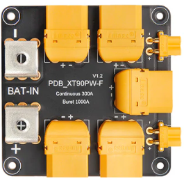
The Holybro Power Distribution Board (PDB) 300A - Side Entry is a high-performance component designed to distribute power efficiently to multiple electronic devices in a circuit. With a maximum current handling capacity of 300A, this PDB is ideal for high-current applications such as drones, RC vehicles, robotics, and other power-intensive projects. Its side entry design simplifies wiring and connections, making it a user-friendly solution for complex setups.

Explore Projects Built with Power Distribution Board (PDB) 300A - Side Entry

Use Cirkit Designer to design, explore, and prototype these projects online. Some projects support real-time simulation. Click "Open Project" to start designing instantly!
Battery-Powered FPV Drone with Telemetry and Dual Motor Control
Image of Krul': A project utilizing Power Distribution Board (PDB) 300A - Side Entry in a practical application
This circuit appears to be a power distribution and control system for a vehicle with two motorized wheels, possibly a drone or a robot. It includes a lipo battery connected to a Power Distribution Board (PDB) that distributes power to two Electronic Speed Controllers (ESCs) which in turn control the speed and direction of the motors. The system also integrates a flight controller (H743-SLIM V3) for managing various peripherals including GPS, FPV camera system, and a telemetry link (ExpressLRS).
Cirkit Designer LogoOpen Project in Cirkit Designer
Industrial Power Distribution and Safety Control System
Image of Control Diagram: A project utilizing Power Distribution Board (PDB) 300A - Side Entry in a practical application
This circuit is designed for power distribution and safety control in an industrial setting. It features a main isolator and circuit breaker for power management, multiple PSUs for 5V, 12V, and 24V outputs, and a safety relay system that interfaces with E-stop buttons and a start switch to control a main contactor, ensuring safe operation and emergency power cut-off capabilities.
Cirkit Designer LogoOpen Project in Cirkit Designer
Battery-Powered USB-C PD Trigger with MP1584EN Power Regulation
Image of BatteriLading: A project utilizing Power Distribution Board (PDB) 300A - Side Entry in a practical application
This circuit is a power management system that uses multiple 18650 Li-ion batteries connected in series to provide a stable power output. The batteries are regulated by MP1584EN power regulator boards, which step down the voltage to a suitable level for the connected USB-C PD trigger board and a power jack. The system ensures a consistent power supply for devices connected to the USB-C port and the power jack.
Cirkit Designer LogoOpen Project in Cirkit Designer
Battery-Powered 18650 Li-ion Charger with USB Output and Adjustable Voltage Regulator
Image of Breadboard: A project utilizing Power Distribution Board (PDB) 300A - Side Entry in a practical application
This circuit is a battery management and power supply system that uses three 3.7V batteries connected to a 3S 10A Li-ion 18650 Charger Protection Board Module for balanced charging and protection. The system includes a TP4056 Battery Charging Protection Module for additional charging safety, a Step Up Boost Power Converter to regulate and boost the voltage, and a USB regulator to provide a stable 5V output, controlled by a push switch.
Cirkit Designer LogoOpen Project in Cirkit Designer

Explore Projects Built with Power Distribution Board (PDB) 300A - Side Entry

Use Cirkit Designer to design, explore, and prototype these projects online. Some projects support real-time simulation. Click "Open Project" to start designing instantly!
Image of Krul': A project utilizing Power Distribution Board (PDB) 300A - Side Entry in a practical application
Battery-Powered FPV Drone with Telemetry and Dual Motor Control
This circuit appears to be a power distribution and control system for a vehicle with two motorized wheels, possibly a drone or a robot. It includes a lipo battery connected to a Power Distribution Board (PDB) that distributes power to two Electronic Speed Controllers (ESCs) which in turn control the speed and direction of the motors. The system also integrates a flight controller (H743-SLIM V3) for managing various peripherals including GPS, FPV camera system, and a telemetry link (ExpressLRS).
Cirkit Designer LogoOpen Project in Cirkit Designer
Image of Control Diagram: A project utilizing Power Distribution Board (PDB) 300A - Side Entry in a practical application
Industrial Power Distribution and Safety Control System
This circuit is designed for power distribution and safety control in an industrial setting. It features a main isolator and circuit breaker for power management, multiple PSUs for 5V, 12V, and 24V outputs, and a safety relay system that interfaces with E-stop buttons and a start switch to control a main contactor, ensuring safe operation and emergency power cut-off capabilities.
Cirkit Designer LogoOpen Project in Cirkit Designer
Image of BatteriLading: A project utilizing Power Distribution Board (PDB) 300A - Side Entry in a practical application
Battery-Powered USB-C PD Trigger with MP1584EN Power Regulation
This circuit is a power management system that uses multiple 18650 Li-ion batteries connected in series to provide a stable power output. The batteries are regulated by MP1584EN power regulator boards, which step down the voltage to a suitable level for the connected USB-C PD trigger board and a power jack. The system ensures a consistent power supply for devices connected to the USB-C port and the power jack.
Cirkit Designer LogoOpen Project in Cirkit Designer
Image of Breadboard: A project utilizing Power Distribution Board (PDB) 300A - Side Entry in a practical application
Battery-Powered 18650 Li-ion Charger with USB Output and Adjustable Voltage Regulator
This circuit is a battery management and power supply system that uses three 3.7V batteries connected to a 3S 10A Li-ion 18650 Charger Protection Board Module for balanced charging and protection. The system includes a TP4056 Battery Charging Protection Module for additional charging safety, a Step Up Boost Power Converter to regulate and boost the voltage, and a USB regulator to provide a stable 5V output, controlled by a push switch.
Cirkit Designer LogoOpen Project in Cirkit Designer

Common Applications and Use Cases

  • Power distribution in high-current drone systems (e.g., FPV racing drones)
  • Robotics projects requiring multiple power outputs
  • RC vehicles with high-power motors and ESCs
  • Custom electronic projects with multiple power-hungry components

Technical Specifications

The following table outlines the key technical details of the Holybro PDB 300A - Side Entry:

Specification Details
Maximum Current Handling 300A
Input Voltage Range 3S to 12S LiPo (11.1V to 50.4V)
Dimensions 68mm x 50mm x 10mm
Weight 36g
Connector Type XT90 (input), solder pads (output)
PCB Material 4-layer PCB with 2oz copper
Operating Temperature -20°C to 85°C
Mounting Hole Spacing 30.5mm x 30.5mm (standard M3 holes)

Pin Configuration and Descriptions

The Holybro PDB 300A features a simple layout with input and output connections. Below is a description of the key connections:

Pin/Connection Description
XT90 Input Main power input for the PDB. Connect to the battery using an XT90 connector.
Positive Output Pads Solder pads for distributing positive voltage to connected components.
Negative Output Pads Solder pads for distributing ground to connected components.
ESC Signal Pads Optional pads for connecting ESC signal wires (if applicable).
Mounting Holes Four M3 holes for securely mounting the PDB to your project.

Usage Instructions

How to Use the Component in a Circuit

  1. Connect the Battery:

    • Use an XT90 connector to connect the battery to the PDB's input port.
    • Ensure the battery voltage is within the supported range (3S to 12S LiPo).
  2. Distribute Power:

    • Solder the positive and negative wires of your components (e.g., ESCs, motors, or other devices) to the corresponding output pads on the PDB.
    • Use high-quality wires capable of handling the required current to avoid overheating.
  3. Secure the PDB:

    • Mount the PDB securely using the M3 mounting holes. Ensure it is insulated from conductive surfaces to prevent short circuits.
  4. Test the Connections:

    • Double-check all connections for proper polarity and secure solder joints.
    • Power on the system and verify that all components receive the correct voltage.

Important Considerations and Best Practices

  • Wire Gauge: Use appropriately thick wires for high-current connections to minimize voltage drops and heat generation.
  • Soldering: Ensure all solder joints are clean and strong to prevent connection failures.
  • Insulation: Use heat shrink tubing or electrical tape to insulate exposed wires and solder joints.
  • Cooling: In high-current applications, ensure adequate airflow around the PDB to prevent overheating.
  • Polarity: Always double-check the polarity of connections to avoid damaging components.

Example: Connecting to an Arduino UNO

While the PDB itself does not directly interface with an Arduino UNO, it can be used to power peripherals connected to the Arduino. Below is an example of powering a motor driver and an Arduino UNO using the PDB:

// Example Arduino code for controlling a motor driver powered by the PDB
// Ensure the motor driver is connected to the PDB's output pads for power.

const int motorPin = 9; // PWM pin connected to the motor driver

void setup() {
  pinMode(motorPin, OUTPUT); // Set motor pin as output
}

void loop() {
  analogWrite(motorPin, 128); // Set motor speed to 50% (PWM value: 128)
  delay(2000);                // Run motor for 2 seconds
  analogWrite(motorPin, 0);   // Stop motor
  delay(2000);                // Wait for 2 seconds
}

Troubleshooting and FAQs

Common Issues and Solutions

  1. No Power Output:

    • Cause: Loose or incorrect connections.
    • Solution: Verify all connections, ensuring proper polarity and secure solder joints.
  2. Overheating:

    • Cause: Excessive current draw or inadequate wire gauge.
    • Solution: Use thicker wires and ensure the total current draw does not exceed 300A.
  3. Short Circuit:

    • Cause: Exposed wires or solder joints touching conductive surfaces.
    • Solution: Insulate all exposed connections and ensure the PDB is mounted on a non-conductive surface.
  4. Voltage Drop:

    • Cause: Long wires or insufficient wire gauge.
    • Solution: Minimize wire length and use low-resistance wires.

FAQs

Q: Can I use this PDB with a 6S LiPo battery?
A: Yes, the PDB supports input voltages from 3S to 12S LiPo batteries, including 6S (22.2V).

Q: Is the PDB compatible with ESCs?
A: Yes, the PDB can distribute power to ESCs. Ensure the ESCs are rated for the battery voltage.

Q: How do I prevent the PDB from overheating?
A: Use proper wire gauge, avoid exceeding the 300A limit, and ensure adequate airflow around the PDB.

Q: Can I use this PDB for non-drone applications?
A: Absolutely! The PDB is suitable for any high-current application requiring efficient power distribution.