How to Use ESP32 (30 pin): Examples, Pinouts, and Specs
Introduction
The ESP32 is a powerful microcontroller developed by Espressif Systems, featuring built-in Wi-Fi and Bluetooth capabilities. With its 30-pin configuration, the ESP32 is designed to support a wide range of input/output functions, making it an excellent choice for Internet of Things (IoT) applications, embedded systems, and smart devices. Its high processing power, low energy consumption, and versatile connectivity options make it a popular choice among hobbyists and professionals alike.
Explore Projects Built with ESP32 (30 pin)


Explore Projects Built with ESP32 (30 pin)
Common Applications and Use Cases
- IoT devices and smart home automation
- Wireless sensor networks
- Wearable technology
- Robotics and drones
- Industrial automation
- Real-time data monitoring and logging
- Prototyping and educational projects
Technical Specifications
The ESP32 (30-pin) microcontroller offers the following key technical features:
| Parameter | Specification |
|---|---|
| Manufacturer | Espressif Systems |
| Part ID | ESP32 |
| Operating Voltage | 3.3V |
| Input Voltage Range | 3.0V to 3.6V |
| Digital I/O Pins | 30 |
| Analog Input Pins | 16 (12-bit ADC) |
| Analog Output Pins | 2 (8-bit DAC) |
| Wi-Fi Standard | 802.11 b/g/n |
| Bluetooth Standard | Bluetooth 4.2 and BLE |
| Flash Memory | 4MB (varies by model) |
| SRAM | 520KB |
| Clock Speed | Up to 240 MHz (dual-core processor) |
| Power Consumption | Ultra-low power in deep sleep mode |
| Communication Protocols | UART, SPI, I2C, I2S, CAN, PWM |
| Operating Temperature | -40°C to +85°C |
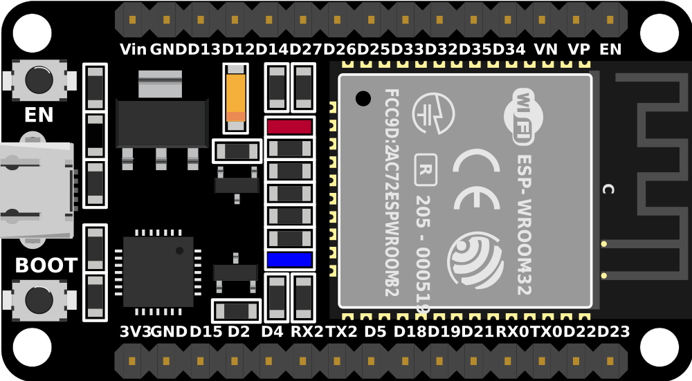
Pin Configuration and Descriptions
The ESP32 (30-pin) microcontroller has the following pinout:
| Pin Number | Pin Name | Description |
|---|---|---|
| 1 | EN | Enable pin (active high, resets the chip) |
| 2 | IO0 | GPIO0, used for boot mode selection |
| 3 | IO1 (TX0) | GPIO1, UART0 TX |
| 4 | IO3 (RX0) | GPIO3, UART0 RX |
| 5 | IO4 | GPIO4, general-purpose I/O |
| 6 | IO5 | GPIO5, general-purpose I/O |
| 7 | IO12 | GPIO12, ADC2 channel 5 |
| 8 | IO13 | GPIO13, ADC2 channel 4 |
| 9 | IO14 | GPIO14, ADC2 channel 6 |
| 10 | IO15 | GPIO15, ADC2 channel 3 |
| 11 | IO16 | GPIO16, general-purpose I/O |
| 12 | IO17 | GPIO17, general-purpose I/O |
| 13 | IO18 | GPIO18, SPI clock (SCK) |
| 14 | IO19 | GPIO19, SPI MISO |
| 15 | IO21 | GPIO21, I2C SDA |
| 16 | IO22 | GPIO22, I2C SCL |
| 17 | IO23 | GPIO23, SPI MOSI |
| 18 | IO25 | GPIO25, DAC1 |
| 19 | IO26 | GPIO26, DAC2 |
| 20 | IO27 | GPIO27, ADC2 channel 7 |
| 21 | IO32 | GPIO32, ADC1 channel 4 |
| 22 | IO33 | GPIO33, ADC1 channel 5 |
| 23 | IO34 | GPIO34, input-only pin |
| 24 | IO35 | GPIO35, input-only pin |
| 25 | GND | Ground |
| 26 | 3V3 | 3.3V power supply |
| 27 | VIN | Input voltage (5V) |
| 28 | IO36 (VP) | GPIO36, ADC1 channel 0 |
| 29 | IO39 (VN) | GPIO39, ADC1 channel 3 |
| 30 | RST | Reset pin |
Usage Instructions
How to Use the ESP32 in a Circuit
- Powering the ESP32: Connect the VIN pin to a 5V power source or use the 3V3 pin for a regulated 3.3V input. Ensure the ground (GND) is connected to the circuit's ground.
- Programming the ESP32: Use a USB-to-serial adapter or a development board with a built-in USB interface. The ESP32 can be programmed using the Arduino IDE, PlatformIO, or Espressif's ESP-IDF.
- Connecting Peripherals: Use the GPIO pins for digital and analog input/output. Ensure the voltage levels of connected devices are compatible with the ESP32's 3.3V logic.
- Wi-Fi and Bluetooth Setup: Configure the Wi-Fi and Bluetooth settings in your code to enable wireless communication.
Important Considerations and Best Practices
- Voltage Levels: The ESP32 operates at 3.3V logic. Avoid connecting 5V signals directly to its pins to prevent damage.
- Boot Mode: GPIO0 must be pulled low during boot to enter programming mode.
- Power Supply: Use a stable power source to avoid unexpected resets or malfunctions.
- Deep Sleep Mode: Utilize the deep sleep mode for low-power applications to extend battery life.
Example Code for Arduino IDE
Below is an example of how to connect the ESP32 to a Wi-Fi network and blink an LED:
#include <WiFi.h> // Include the Wi-Fi library

const char* ssid = "Your_SSID";       // Replace with your Wi-Fi SSID
const char* password = "Your_PASSWORD"; // Replace with your Wi-Fi password
const int ledPin = 2;                 // GPIO2 is connected to the onboard LED

void setup() {
  pinMode(ledPin, OUTPUT);            // Set the LED pin as an output
  Serial.begin(115200);               // Start the serial communication
  WiFi.begin(ssid, password);         // Connect to the Wi-Fi network

  Serial.print("Connecting to Wi-Fi");
  while (WiFi.status() != WL_CONNECTED) {
    delay(500);
    Serial.print(".");
  }
  Serial.println("\nConnected to Wi-Fi");
}

void loop() {
  digitalWrite(ledPin, HIGH);         // Turn the LED on
  delay(1000);                        // Wait for 1 second
  digitalWrite(ledPin, LOW);          // Turn the LED off
  delay(1000);                        // Wait for 1 second
}
Troubleshooting and FAQs
Common Issues and Solutions
ESP32 Not Connecting to Wi-Fi
- Ensure the SSID and password are correct.
- Check if the Wi-Fi network is within range.
- Verify that the router supports 2.4 GHz, as the ESP32 does not support 5 GHz.
ESP32 Not Entering Programming Mode
- Ensure GPIO0 is pulled low during boot.
- Check the USB connection and drivers for the USB-to-serial adapter.
Random Resets or Instability
- Use a stable power supply with sufficient current (at least 500mA).
- Add decoupling capacitors near the power pins to reduce noise.
GPIO Pins Not Working
- Verify the pin configuration in your code.
- Check if the pin is being used for another function (e.g., ADC, UART).
FAQs
Can the ESP32 operate on battery power? Yes, the ESP32 can be powered by a battery. Use a voltage regulator to ensure the input voltage is within the 3.0V to 3.6V range.
How do I update the ESP32 firmware? Use the Espressif Flash Download Tool or the Arduino IDE to upload new firmware.
Can I use the ESP32 with 5V peripherals? Use a level shifter to safely interface 5V peripherals with the ESP32's 3.3V logic.
This documentation provides a comprehensive guide to using the ESP32 (30-pin) microcontroller effectively. For further details, refer to the official Espressif documentation.