How to Use Multiplexer: Examples, Pinouts, and Specs
Introduction
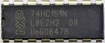
A multiplexer, often abbreviated as "MUX," is an electronic component that selects one of several input signals and forwards the selected input to a single output line. The 74HC151N, manufactured by Mani, is a high-speed CMOS 8-to-1 multiplexer. It is widely used in digital circuits for data routing, signal selection, and switching applications. This component is particularly useful in scenarios where multiple data sources need to be transmitted over a single communication line.
Explore Projects Built with Multiplexer


Explore Projects Built with Multiplexer
Common Applications
- Data selection and routing in digital systems
- Signal multiplexing in communication systems
- Memory addressing in microcontroller-based designs
- Logic function generation
- Analog-to-digital conversion (ADC) systems
Technical Specifications
Key Technical Details
| Parameter | Value |
|---|---|
| Manufacturer | Mani |
| Part Number | 74HC151N |
| Supply Voltage (Vcc) | 2V to 6V |
| Input Voltage Range | 0V to Vcc |
| Maximum Output Current | ±25mA |
| Propagation Delay | ~16ns (at 5V) |
| Operating Temperature | -40°C to +125°C |
| Package Type | DIP-16 |
Pin Configuration and Descriptions
The 74HC151N comes in a 16-pin Dual Inline Package (DIP). Below is the pinout and description:
| Pin Number | Name | Description |
|---|---|---|
| 1 | A | Select Line A (LSB) |
| 2 | B | Select Line B |
| 3 | C | Select Line C (MSB) |
| 4 | Y | Multiplexer Output |
| 5 | W | Complementary Output (Inverted Y) |
| 6 | I3 | Data Input 3 |
| 7 | I2 | Data Input 2 |
| 8 | GND | Ground (0V) |
| 9 | I1 | Data Input 1 |
| 10 | I0 | Data Input 0 |
| 11 | I7 | Data Input 7 |
| 12 | I6 | Data Input 6 |
| 13 | I5 | Data Input 5 |
| 14 | I4 | Data Input 4 |
| 15 | G | Enable Input (Active Low) |
| 16 | Vcc | Positive Supply Voltage |
Usage Instructions
How to Use the 74HC151N in a Circuit
- Power Supply: Connect the Vcc pin (16) to a positive voltage source (2V to 6V) and the GND pin (8) to ground.
- Data Inputs: Connect up to 8 data sources to the input pins I0 to I7.
- Select Lines: Use the select pins A, B, and C to choose which input (I0–I7) is routed to the output. The binary combination of these pins determines the selected input.
- For example, if A=0, B=1, and C=0, the multiplexer will select I2.
- Enable Pin: The G pin is an active-low enable input. Ensure this pin is connected to ground (logic LOW) to enable the multiplexer. If this pin is HIGH, the output will be disabled.
- Output: The selected input signal will appear on the Y pin. The inverted version of the output is available on the W pin.
Important Considerations
- Ensure the supply voltage does not exceed the maximum rating of 6V to avoid damaging the component.
- Use pull-up or pull-down resistors on unused input pins to prevent floating inputs, which can cause unpredictable behavior.
- The propagation delay (~16ns at 5V) should be considered in high-speed applications.
- Avoid exceeding the maximum output current of ±25mA to prevent overheating or damage.
Example: Connecting the 74HC151N to an Arduino UNO
Below is an example of how to use the 74HC151N with an Arduino UNO to select and read one of eight input signals.
Circuit Connections
- Connect Vcc to the Arduino's 5V pin and GND to the Arduino's GND.
- Connect the select pins A, B, and C to Arduino digital pins 2, 3, and 4, respectively.
- Connect the G pin to GND to enable the multiplexer.
- Connect the Y pin to an Arduino analog input pin (e.g., A0).
- Connect your data sources to the input pins I0 to I7.
Arduino Code
// Define select pins
const int selectPinA = 2; // Connect to pin A of 74HC151N
const int selectPinB = 3; // Connect to pin B of 74HC151N
const int selectPinC = 4; // Connect to pin C of 74HC151N

// Define multiplexer output pin
const int muxOutputPin = A0; // Connect to pin Y of 74HC151N

void setup() {
  // Set select pins as outputs
  pinMode(selectPinA, OUTPUT);
  pinMode(selectPinB, OUTPUT);
  pinMode(selectPinC, OUTPUT);

  // Initialize serial communication for debugging
  Serial.begin(9600);
}

void loop() {
  for (int i = 0; i < 8; i++) {
    // Set the select pins to the binary representation of i
    digitalWrite(selectPinA, i & 0x01); // LSB
    digitalWrite(selectPinB, (i >> 1) & 0x01);
    digitalWrite(selectPinC, (i >> 2) & 0x01); // MSB

    // Read the selected input
    int value = analogRead(muxOutputPin);

    // Print the value to the serial monitor
    Serial.print("Input ");
    Serial.print(i);
    Serial.print(": ");
    Serial.println(value);

    delay(500); // Wait for 500ms before reading the next input
  }
}
Troubleshooting and FAQs
Common Issues
No Output Signal on Y Pin
- Ensure the G pin is connected to ground (logic LOW) to enable the multiplexer.
- Verify that the select pins (A, B, C) are correctly configured to select the desired input.
Unstable or Noisy Output
- Check for floating input pins. Use pull-up or pull-down resistors on unused inputs.
- Ensure the power supply is stable and within the specified range (2V to 6V).
Component Overheating
- Verify that the output current does not exceed ±25mA.
- Check for short circuits or incorrect wiring.
FAQs
Q: Can the 74HC151N handle analog signals?
A: The 74HC151N is designed for digital signals. While it can pass low-frequency analog signals, it is not optimized for high-precision analog applications.
Q: What happens if the enable pin (G) is HIGH?
A: When the G pin is HIGH, the multiplexer is disabled, and the output pins Y and W will not reflect any input signal.
Q: Can I cascade multiple 74HC151N multiplexers?
A: Yes, you can cascade multiple multiplexers to handle more inputs. For example, two 74HC151N chips can be used to select from 16 inputs.