How to Use Phototransistor: Examples, Pinouts, and Specs
Introduction
A phototransistor is a semiconductor device that operates as a light-sensitive transistor. It is similar to a regular bipolar junction transistor (BJT), except that it is activated by photons rather than an electrical current at the base terminal. Phototransistors are widely used in electronic circuits for light detection and signal amplification, making them essential components in devices such as light sensors, optoisolators, and certain types of communication equipment.
Explore Projects Built with Phototransistor
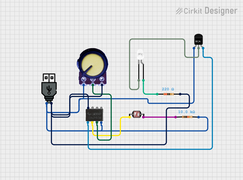
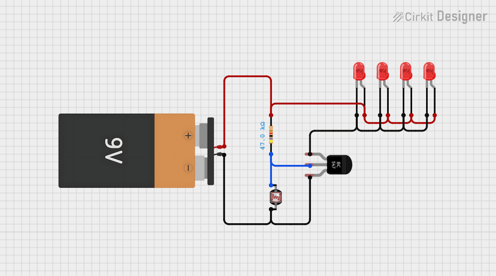
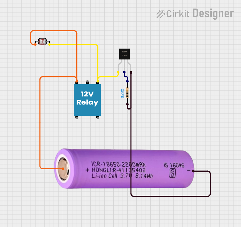
Explore Projects Built with Phototransistor
Common Applications and Use Cases
- Ambient light sensing
- Optical switches
- Infrared receivers
- Non-contact position sensing
- Safety barriers and object detection in industrial automation
Technical Specifications
Key Technical Details
- Material: Silicon or other semiconductor materials
- Wavelength Sensitivity: Typically in the range of infrared to visible light
- Collector-Emitter Voltage (Vce): Maximum voltage that can be applied across the collector-emitter terminals
- Collector Current (Ic): Maximum current that can flow through the collector-emitter terminals
- Power Dissipation: Maximum power the phototransistor can dissipate without damage
Pin Configuration and Descriptions
| Pin Number | Name | Description |
|---|---|---|
| 1 | Emitter (E) | Current flows out through this terminal; connected to ground in most circuits |
| 2 | Collector (C) | Current flows in through this terminal; connected to the positive supply through a load |
| 3 | Base (B) | Typically left unconnected or used for sensitivity control as it is light-sensitive |
Usage Instructions
How to Use the Phototransistor in a Circuit
- Connect the Collector: The collector pin should be connected to the positive voltage supply through a suitable load resistor. This resistor determines the sensitivity and output voltage range.
- Emitter Connection: Connect the emitter pin to the ground of the circuit.
- Light Exposure: Ensure that the phototransistor is positioned to receive adequate light for the application.
- Output Signal: The voltage across the load resistor serves as the output signal, which varies with light intensity.
Important Considerations and Best Practices
- Load Resistor Selection: Choose a load resistor that provides the desired sensitivity and output voltage range for your application.
- Ambient Light: Be aware of the ambient light conditions, as they can affect the performance of the phototransistor.
- Filtering: Use optical filters to block unwanted wavelengths of light if necessary.
- Temperature: Consider the operating temperature range, as extreme temperatures can affect the phototransistor's performance.
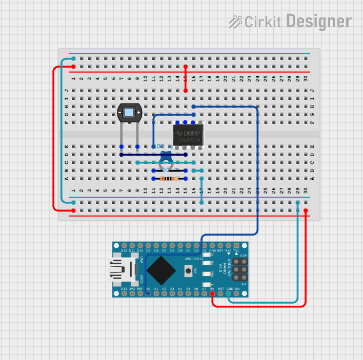
Example Circuit with Arduino UNO
// Define the phototransistor pin
const int phototransistorPin = A0; // Analog input pin A0

void setup() {
  // Initialize serial communication at 9600 baud rate
  Serial.begin(9600);
}

void loop() {
  // Read the value from the phototransistor
  int sensorValue = analogRead(phototransistorPin);

  // Convert the reading to a voltage
  float voltage = sensorValue * (5.0 / 1023.0);

  // Print the voltage to the Serial Monitor
  Serial.println(voltage);

  // Wait for a bit to get stable readings
  delay(200);
}
Troubleshooting and FAQs
Common Issues Users Might Face
- Low Sensitivity: If the phototransistor seems to have low sensitivity, check the load resistor value and adjust it accordingly.
- Ambient Light Interference: If ambient light is affecting the readings, consider using an optical filter or shroud to isolate the phototransistor from unwanted light sources.
- Erratic Readings: Ensure that all connections are secure and that there is no electrical noise affecting the circuit.
Solutions and Tips for Troubleshooting
- Check Connections: Verify that all connections are correct and secure.
- Resistor Value Adjustment: Experiment with different load resistor values to find the optimal sensitivity.
- Use of Filters: Apply optical filters to block out specific wavelengths of light that may be causing interference.
- Shielding: Use shielding to protect the circuit from electromagnetic interference.
FAQs
Q: Can I use a phototransistor to detect specific colors of light? A: Phototransistors generally respond to a broad range of wavelengths. For color-specific applications, consider using a color sensor or applying optical filters.
Q: How do I increase the range of detection for a phototransistor? A: To increase the range, you can use a lens to focus light onto the phototransistor or increase the intensity of the light source.
Q: What is the difference between a phototransistor and a photodiode? A: A photodiode is designed to generate a current proportional to light intensity, while a phototransistor amplifies this current, resulting in greater sensitivity.