
How to Use Arduino Pro Mini (3.3V): Examples, Pinouts, and Specs
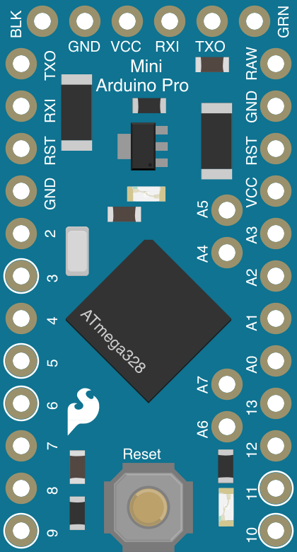
 Design with Arduino Pro Mini (3.3V) in Cirkit Designer
Introduction
The Arduino Pro Mini (3.3V), manufactured by SparkFun (Part ID: DEV-11114), is a compact and lightweight microcontroller board based on the ATmega328P. Designed for low-power applications, it operates at 3.3V and runs at a clock speed of 8 MHz. This board is ideal for projects where space and power efficiency are critical. It features 14 digital input/output pins (6 of which can be used as PWM outputs) and 6 analog input pins, making it versatile for a wide range of embedded applications.
Explore Projects Built with Arduino Pro Mini (3.3V)
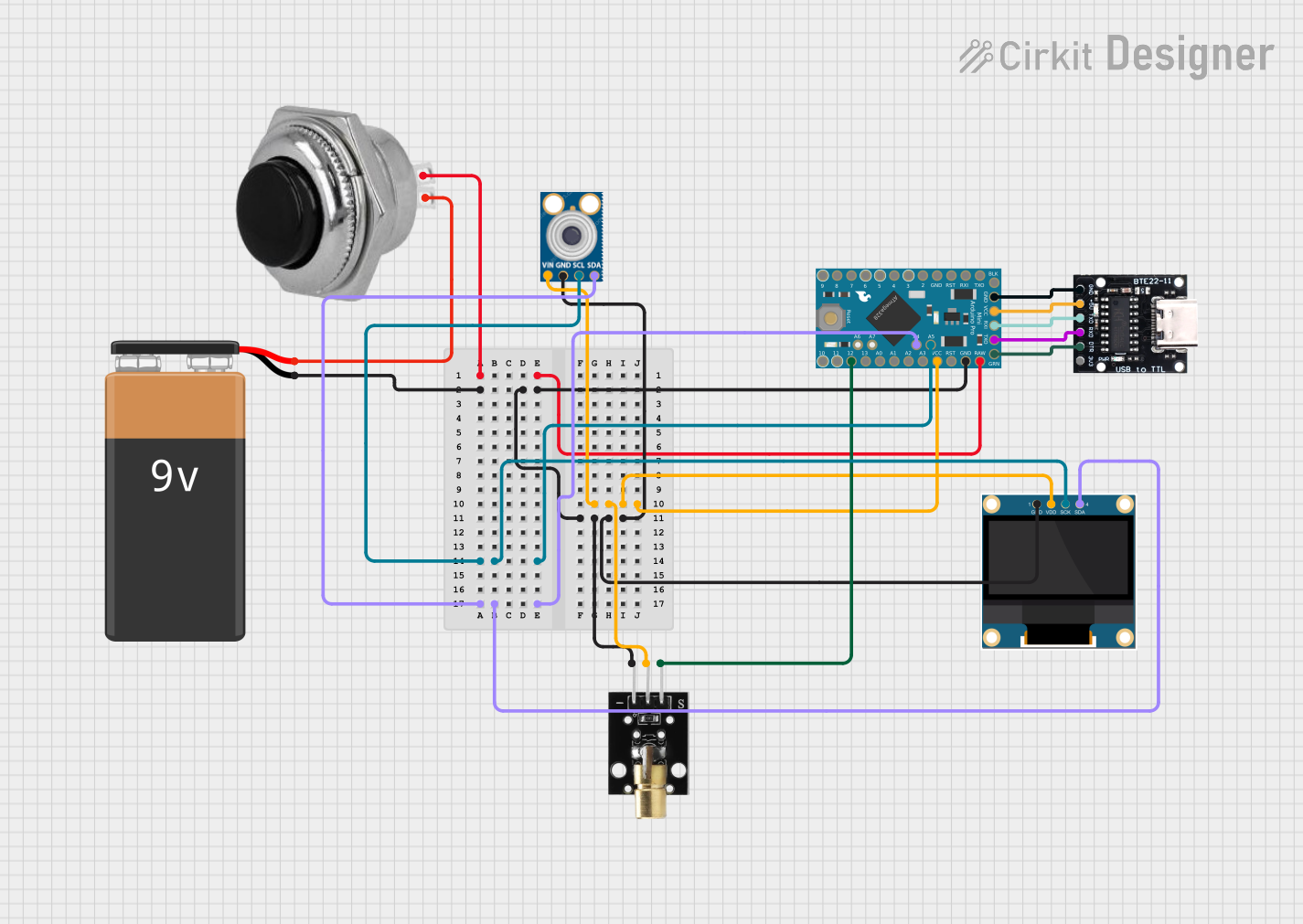 Open Project in Cirkit Designer
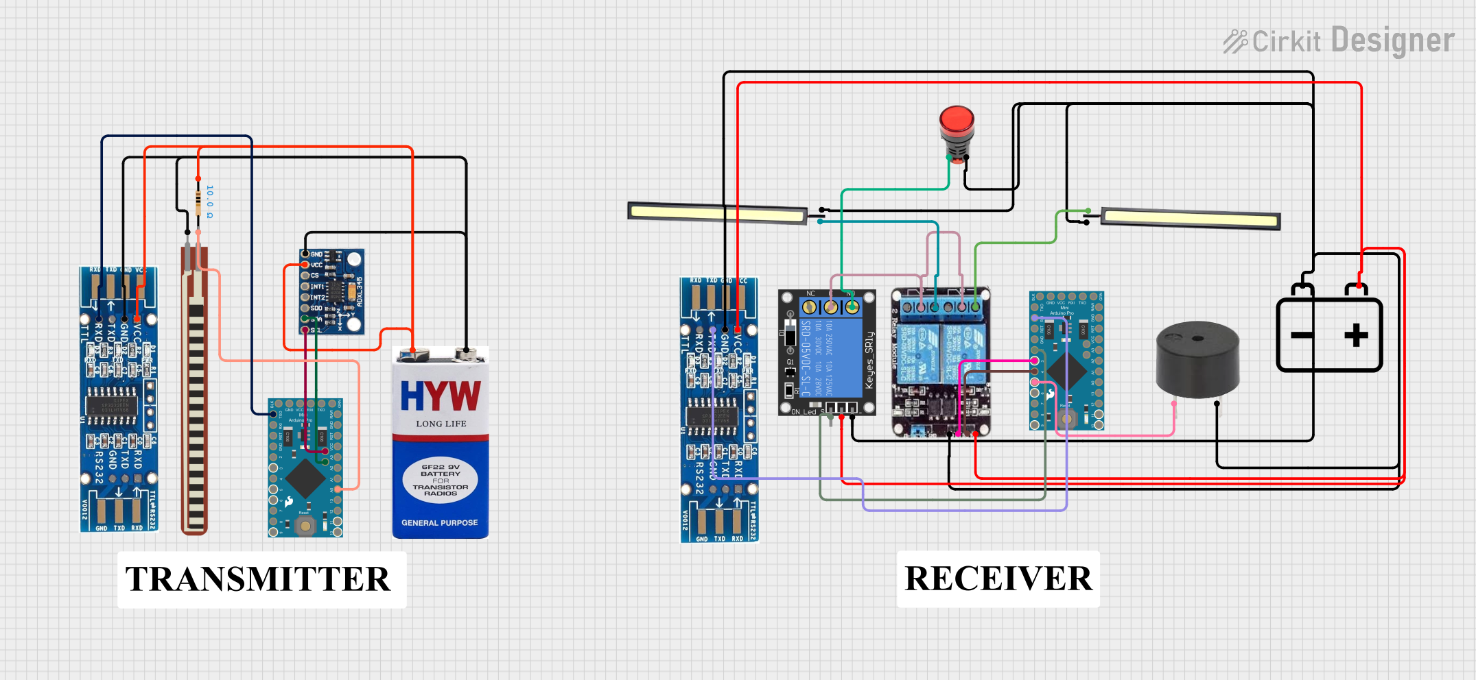 Open Project in Cirkit Designer
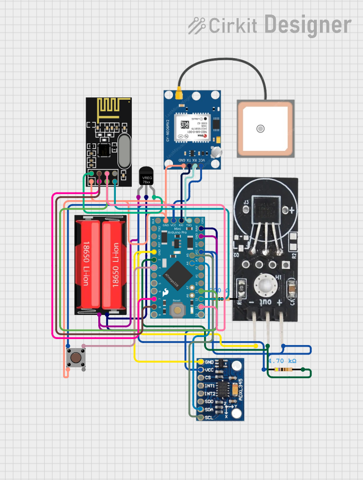 Open Project in Cirkit Designer
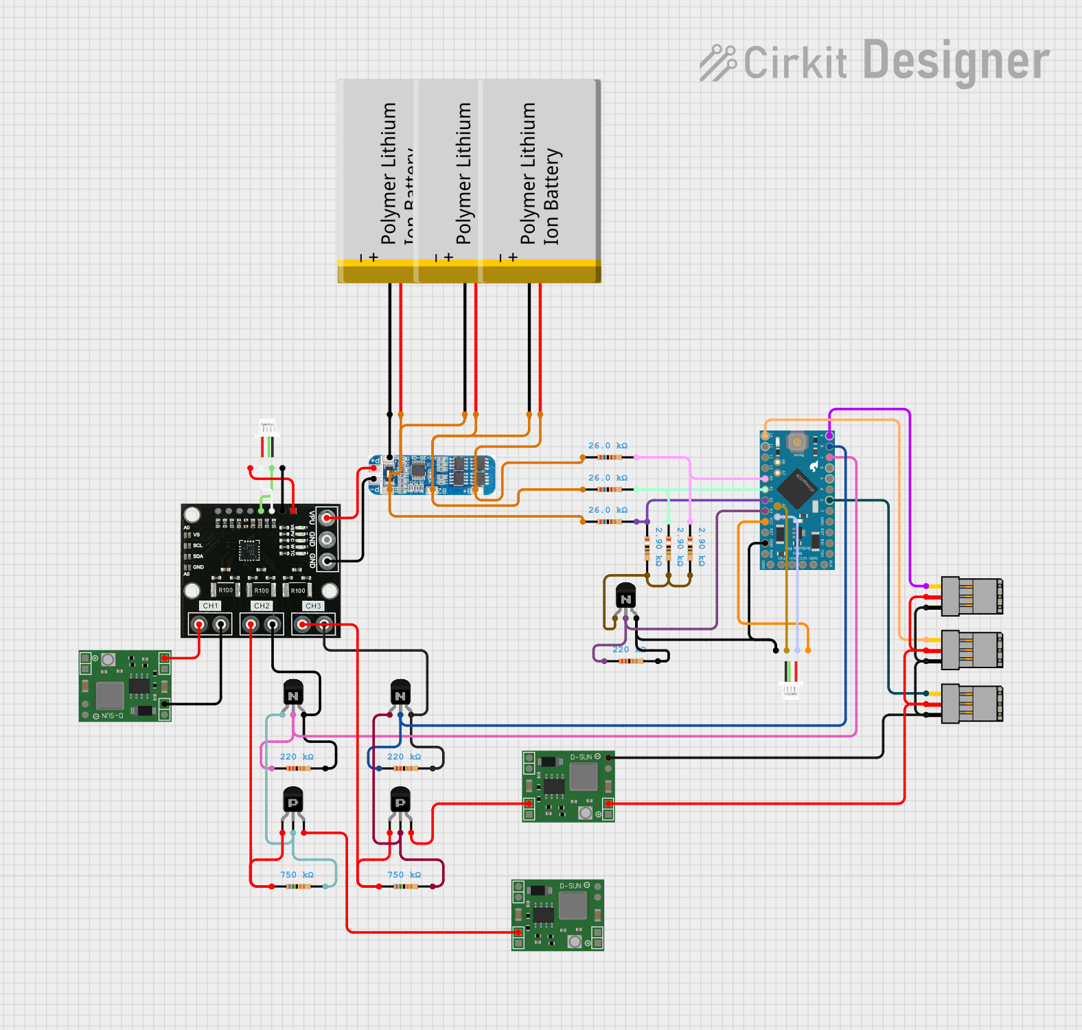 Open Project in Cirkit Designer
Explore Projects Built with Arduino Pro Mini (3.3V)
Open Project in Cirkit DesignerOpen Project in Cirkit DesignerOpen Project in Cirkit DesignerOpen Project in Cirkit DesignerCommon Applications and Use Cases
- Battery-powered IoT devices
- Wearable electronics
- Sensor data acquisition
- Robotics and automation
- Prototyping compact embedded systems
Technical Specifications
Below are the key technical details of the Arduino Pro Mini (3.3V):
| Specification | Details |
|---|---|
| Microcontroller | ATmega328P |
| Operating Voltage | 3.3V |
| Clock Speed | 8 MHz |
| Digital I/O Pins | 14 (6 PWM outputs) |
| Analog Input Pins | 6 |
| Flash Memory | 32 KB (0.5 KB used by bootloader) |
| SRAM | 2 KB |
| EEPROM | 1 KB |
| Power Supply | 3.3V regulated or 3.3V-12V unregulated |
| Dimensions | 18 mm x 33 mm |
Pin Configuration and Descriptions
The Arduino Pro Mini (3.3V) has a total of 24 pins. Below is the pinout description:
| Pin | Type | Description |
|---|---|---|
| RAW | Power Input | Unregulated power input (3.3V-12V). Internally regulated to 3.3V. |
| VCC | Power Output | Regulated 3.3V output. |
| GND | Ground | Ground connection. |
| TX | Digital Output | UART Transmit pin for serial communication. |
| RX | Digital Input | UART Receive pin for serial communication. |
| D0-D13 | Digital I/O | General-purpose digital input/output pins. D3, D5, D6, D9, D10, and D11 support PWM. |
| A0-A5 | Analog Input | Analog input pins (10-bit resolution). |
| RST | Reset | Resets the microcontroller when pulled LOW. |
Usage Instructions
How to Use the Arduino Pro Mini (3.3V) in a Circuit
Powering the Board:
- Connect a regulated 3.3V power source to the
VCCpin. - Alternatively, supply an unregulated voltage (3.3V-12V) to the
RAWpin. The onboard voltage regulator will step it down to 3.3V. - Ensure the power source can supply sufficient current for your application.
- Connect a regulated 3.3V power source to the
Programming the Board:
- The Arduino Pro Mini does not have a built-in USB interface. Use an external USB-to-Serial adapter (e.g., FTDI Basic Breakout) to upload code.
- Connect the adapter to the
TX,RX,VCC,GND, andDTRpins. TheDTRpin allows the board to reset automatically during programming.
Connecting Peripherals:
- Use the digital I/O pins (D0-D13) for interfacing with LEDs, sensors, or other digital devices.
- Use the analog input pins (A0-A5) for reading sensor data or other analog signals.
Uploading Code:
- Select "Arduino Pro or Pro Mini" as the board type in the Arduino IDE.
- Choose the processor as "ATmega328P (3.3V, 8 MHz)".
- Upload your sketch using the external USB-to-Serial adapter.
Important Considerations and Best Practices
- Voltage Levels: Ensure all connected peripherals operate at 3.3V logic levels to avoid damaging the board.
- Power Consumption: For battery-powered applications, minimize power usage by disabling unused peripherals and using sleep modes.
- Soldering: The board comes without headers pre-soldered. Solder headers or wires as needed for your project.
- Heat Dissipation: Avoid exceeding the maximum current ratings of the onboard voltage regulator to prevent overheating.
Example Code for Arduino Pro Mini (3.3V)
Below is an example code to blink an LED connected to pin D13:
// Blink an LED connected to pin D13
// This example demonstrates basic digital output functionality.

const int ledPin = 13; // Pin connected to the LED

void setup() {
  pinMode(ledPin, OUTPUT); // Set pin D13 as an output
}

void loop() {
  digitalWrite(ledPin, HIGH); // Turn the LED on
  delay(1000);               // Wait for 1 second
  digitalWrite(ledPin, LOW);  // Turn the LED off
  delay(1000);               // Wait for 1 second
}
Troubleshooting and FAQs
Common Issues and Solutions
Problem: The board is not detected by the Arduino IDE.
- Solution: Ensure the USB-to-Serial adapter is properly connected to the board. Check that the correct COM port and board type are selected in the Arduino IDE.
Problem: Code upload fails with a timeout error.
- Solution: Verify the
DTRpin is connected to the USB-to-Serial adapter. This pin is required for automatic resetting during programming.
- Solution: Verify the
Problem: The board overheats during operation.
- Solution: Check the input voltage on the
RAWpin. Ensure it does not exceed 12V. Also, verify that connected peripherals do not draw excessive current.
- Solution: Check the input voltage on the
Problem: Analog readings are inaccurate.
- Solution: Ensure the input voltage to the
VCCpin is stable and within the specified range. Use proper decoupling capacitors if necessary.
- Solution: Ensure the input voltage to the
FAQs
Q: Can I power the board directly with a LiPo battery?
- A: Yes, you can connect a single-cell LiPo battery (3.7V nominal) to the
RAWpin. The onboard regulator will step it down to 3.3V.
- A: Yes, you can connect a single-cell LiPo battery (3.7V nominal) to the
Q: Can I use 5V sensors with this board?
- A: No, the Arduino Pro Mini (3.3V) operates at 3.3V logic levels. Use level shifters or 3.3V-compatible sensors.
Q: How do I reduce power consumption for battery-powered projects?
- A: Use the
LowPowerlibrary to put the ATmega328P into sleep mode when idle. Disable unused peripherals like the ADC or timers.
- A: Use the
This concludes the documentation for the Arduino Pro Mini (3.3V). For additional resources, visit the SparkFun product page.