
How to Use EMERGENCY BUTTON: Examples, Pinouts, and Specs
 Design with EMERGENCY BUTTON in Cirkit Designer
Introduction
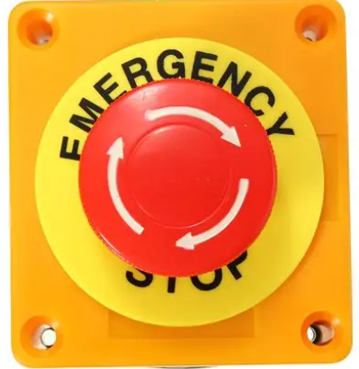
The EMERGENCY BUTTON (Manufacturer: SIFA LAB, Part ID: EMERGENCY) is a safety device designed to provide an immediate response in critical situations. When pressed, it triggers an alert or activates safety protocols, ensuring rapid action during emergencies. This component is widely used in industrial machinery, public safety systems, and home automation setups to enhance safety and reliability.
Explore Projects Built with EMERGENCY BUTTON
 Open Project in Cirkit Designer
 Open Project in Cirkit Designer
 Open Project in Cirkit Designer
 Open Project in Cirkit Designer
Explore Projects Built with EMERGENCY BUTTON
Open Project in Cirkit DesignerOpen Project in Cirkit DesignerOpen Project in Cirkit DesignerOpen Project in Cirkit DesignerCommon Applications
- Industrial machinery shutdown systems
- Emergency stop mechanisms in factories
- Public safety alert systems
- Home automation for panic or distress signals
- Elevator emergency stop buttons
Technical Specifications
Key Technical Details
| Parameter | Value |
|---|---|
| Manufacturer | SIFA LAB |
| Part ID | EMERGENCY |
| Operating Voltage | 12V DC (typical) |
| Maximum Current Rating | 3A |
| Contact Type | Normally Open (NO) or Normally Closed (NC) |
| Button Type | Latching (push to activate, twist to reset) |
| Operating Temperature | -20°C to 70°C |
| Dimensions | 40mm diameter, 50mm height |
| Mounting Type | Panel mount |
| Material | Polycarbonate (button), metal (contacts) |
Pin Configuration and Descriptions
The EMERGENCY BUTTON typically has four terminals for wiring. The pin configuration is as follows:
| Pin Label | Description |
|---|---|
| NO | Normally Open contact. Closes when the button is pressed. |
| NC | Normally Closed contact. Opens when the button is pressed. |
| COM | Common terminal. Connects to either NO or NC based on the circuit. |
| GND | Ground terminal for electrical connection. |
Usage Instructions
How to Use the Component in a Circuit
Wiring the Button:
- Identify the required contact type for your application (NO or NC).
- Connect the COM terminal to the power source or signal line.
- Connect the NO terminal to the load or device to be activated when the button is pressed.
- Optionally, connect the NC terminal if you need a normally closed circuit.
Mounting:
- Drill a hole in the panel with a diameter of 22mm to 25mm.
- Insert the button into the hole and secure it using the provided locking nut.
Testing:
- After wiring, press the button to ensure it activates the desired response.
- Twist the button to reset it to its original state.
Important Considerations and Best Practices
- Ensure the button is rated for the voltage and current of your application.
- Use proper insulation and secure connections to avoid short circuits.
- For safety-critical applications, test the button regularly to ensure functionality.
- Avoid exposing the button to excessive moisture or dust unless it is installed in a protected enclosure.
Example: Connecting to an Arduino UNO
The EMERGENCY BUTTON can be used with an Arduino UNO to trigger an alert or stop a process. Below is an example circuit and code:
Circuit Setup
- Connect the COM terminal to the Arduino's 5V pin.
- Connect the NO terminal to a digital input pin (e.g., pin 2).
- Use a pull-down resistor (10kΩ) between the NO terminal and GND to ensure a stable signal.
Arduino Code
// Emergency Button Example Code
// This code monitors the button state and triggers an alert when pressed.

const int buttonPin = 2;  // Pin connected to the NO terminal of the button
const int ledPin = 13;    // Built-in LED for visual alert

void setup() {
  pinMode(buttonPin, INPUT);  // Set button pin as input
  pinMode(ledPin, OUTPUT);   // Set LED pin as output
  digitalWrite(ledPin, LOW); // Ensure LED is off initially
  Serial.begin(9600);        // Initialize serial communication
}

void loop() {
  int buttonState = digitalRead(buttonPin); // Read the button state

  if (buttonState == HIGH) { // If button is pressed
    digitalWrite(ledPin, HIGH); // Turn on the LED
    Serial.println("Emergency Button Pressed!"); // Print alert message
  } else {
    digitalWrite(ledPin, LOW); // Turn off the LED
  }

  delay(100); // Small delay to debounce the button
}
Troubleshooting and FAQs
Common Issues and Solutions
Button Does Not Trigger Any Response:
- Check the wiring connections, especially the COM and NO/NC terminals.
- Verify that the button is not damaged or stuck in the pressed state.
Button Stays Activated After Pressing:
- Ensure the button is properly reset by twisting it.
- Check for mechanical obstructions or debris around the button.
Arduino Does Not Detect Button Press:
- Confirm the pull-down resistor is correctly connected.
- Verify the Arduino pin configuration in the code matches the wiring.
Button Feels Loose or Wobbly:
- Tighten the locking nut to secure the button to the panel.
FAQs
Q: Can this button be used outdoors?
A: The EMERGENCY BUTTON is not waterproof. For outdoor use, install it in a weatherproof enclosure.
Q: What is the difference between NO and NC contacts?
A: NO (Normally Open) contacts close the circuit when the button is pressed, while NC (Normally Closed) contacts open the circuit when the button is pressed.
Q: Can I use this button with AC circuits?
A: Yes, as long as the voltage and current ratings (up to 3A) are not exceeded.
Q: How often should I test the button?
A: For safety-critical applications, test the button at least once a month to ensure proper functionality.