
How to Use Noctua PWM FAN: Examples, Pinouts, and Specs
 Design with Noctua PWM FAN in Cirkit Designer
Introduction
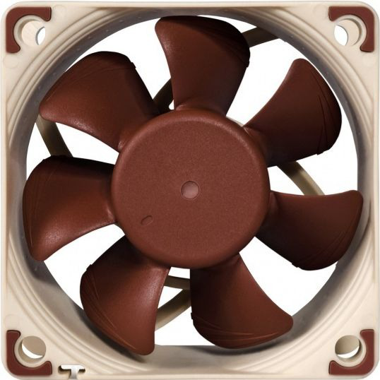
The Noctua PWM FAN is a high-performance cooling fan designed for applications requiring efficient airflow and noise reduction. It features Pulse Width Modulation (PWM) control, enabling precise speed adjustments to optimize cooling performance while minimizing noise levels. This makes it ideal for use in computer systems, electronics enclosures, and other thermal management applications.
Explore Projects Built with Noctua PWM FAN
 Open Project in Cirkit Designer
 Open Project in Cirkit Designer
 Open Project in Cirkit Designer
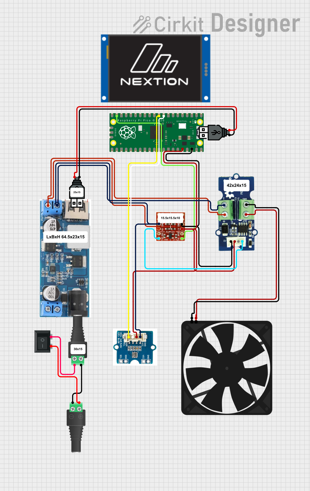 Open Project in Cirkit Designer
Explore Projects Built with Noctua PWM FAN
Open Project in Cirkit DesignerOpen Project in Cirkit DesignerOpen Project in Cirkit DesignerOpen Project in Cirkit DesignerCommon Applications and Use Cases
- Cooling for computer CPUs, GPUs, and cases
- Thermal management in electronics enclosures
- Custom cooling solutions for DIY projects
- Integration into robotics and automation systems
- Use in temperature-sensitive environments requiring quiet operation
Technical Specifications
The Noctua PWM FAN is available in various models, but the following specifications are typical for a standard 120mm Noctua PWM fan:
| Parameter | Value |
|---|---|
| Operating Voltage | 12V DC |
| Input Current | 0.05A to 0.15A (depending on load) |
| Power Consumption | 0.6W to 1.8W |
| Speed Range (PWM Control) | 300 RPM to 1500 RPM |
| Airflow | Up to 93.4 m³/h (55 CFM) |
| Noise Level | 18.1 dB(A) |
| Connector Type | 4-pin PWM |
| Bearing Type | SSO2 (Self-Stabilizing Oil) |
| Dimensions | 120mm x 120mm x 25mm |
Pin Configuration and Descriptions
The Noctua PWM FAN uses a standard 4-pin connector for PWM control. The pinout is as follows:
| Pin | Name | Description |
|---|---|---|
| 1 | GND | Ground connection for the fan |
| 2 | +12V | Power supply for the fan (12V DC) |
| 3 | Sense (Tach) | Tachometer output for monitoring fan speed |
| 4 | PWM | Pulse Width Modulation input for controlling fan speed (active high, 25kHz max) |
Usage Instructions
How to Use the Noctua PWM FAN in a Circuit
- Power Connection: Connect the GND pin to the ground of your power supply and the +12V pin to a 12V DC power source.
- PWM Control: Use a microcontroller (e.g., Arduino) or a dedicated PWM controller to send a PWM signal to the PWM pin. The duty cycle of the PWM signal determines the fan speed:
- 0% duty cycle: Fan stops (if supported by the model)
- 100% duty cycle: Fan runs at maximum speed
- Tachometer Monitoring: Connect the Sense (Tach) pin to a microcontroller or monitoring system to measure the fan's RPM. The tachometer signal outputs two pulses per revolution.
Important Considerations and Best Practices
- PWM Signal Frequency: Ensure the PWM signal frequency is within the fan's supported range (typically 25kHz).
- Power Supply: Use a stable 12V DC power source to avoid damaging the fan.
- Mounting: Secure the fan using the provided anti-vibration mounts or screws to minimize noise and vibration.
- Airflow Direction: Check the airflow direction indicated on the fan housing to ensure proper installation.
- Temperature Monitoring: For optimal performance, use a temperature sensor to dynamically adjust the fan speed based on thermal conditions.
Example: Connecting the Noctua PWM FAN to an Arduino UNO
Below is an example of how to control the Noctua PWM FAN using an Arduino UNO:
// Example code to control a Noctua PWM FAN with an Arduino UNO
// The fan's PWM pin is connected to pin 9 on the Arduino
// The fan's GND and +12V pins are connected to an external 12V power supply

const int pwmPin = 9; // Arduino pin connected to the fan's PWM pin
int fanSpeed = 128;   // Initial fan speed (0-255, where 255 is 100% duty cycle)

void setup() {
  pinMode(pwmPin, OUTPUT); // Set the PWM pin as an output
}

void loop() {
  analogWrite(pwmPin, fanSpeed); // Set the fan speed using PWM
  delay(5000);                  // Run at this speed for 5 seconds

  // Gradually increase fan speed
  for (fanSpeed = 128; fanSpeed <= 255; fanSpeed += 5) {
    analogWrite(pwmPin, fanSpeed); // Update fan speed
    delay(100);                   // Wait 100ms between updates
  }

  // Gradually decrease fan speed
  for (fanSpeed = 255; fanSpeed >= 128; fanSpeed -= 5) {
    analogWrite(pwmPin, fanSpeed); // Update fan speed
    delay(100);                   // Wait 100ms between updates
  }
}
Troubleshooting and FAQs
Common Issues and Solutions
Fan Does Not Spin
- Cause: No power or incorrect wiring.
- Solution: Verify the GND and +12V connections. Ensure the power supply is providing 12V DC.
Fan Runs at Full Speed Constantly
- Cause: PWM signal not connected or incorrect frequency.
- Solution: Check the PWM connection and ensure the signal frequency is within the supported range (25kHz).
Fan Speed Does Not Change
- Cause: Incorrect PWM duty cycle or faulty PWM signal.
- Solution: Verify the PWM signal using an oscilloscope. Ensure the duty cycle is being adjusted correctly.
Excessive Noise or Vibration
- Cause: Improper mounting or damaged fan.
- Solution: Re-mount the fan using anti-vibration mounts. Inspect the fan for physical damage.
FAQs
Can I use the Noctua PWM FAN with a 5V power supply?
- No, the fan requires a 12V DC power supply for proper operation.
What happens if I don't connect the PWM pin?
- The fan will run at its default speed, which is typically the maximum speed.
Can I control multiple fans with one PWM signal?
- Yes, you can control multiple fans with a single PWM signal, but ensure the power supply can handle the combined current draw.
Is the fan waterproof?
- No, the Noctua PWM FAN is not waterproof and should not be exposed to liquids.
By following this documentation, you can effectively integrate the Noctua PWM FAN into your projects for efficient and quiet cooling.