
How to Use 4 pin header: Examples, Pinouts, and Specs

 Design with 4 pin header in Cirkit Designer
Introduction
A 4 pin header is a type of electrical connector consisting of four pins arranged in a single row. It is widely used in electronic circuits to establish connections between components, modules, or wires. These headers are versatile and can be used for both signal and power connections. They are commonly found in breadboards, PCBs, and microcontroller projects.
Explore Projects Built with 4 pin header
 Open Project in Cirkit Designer
 Open Project in Cirkit Designer
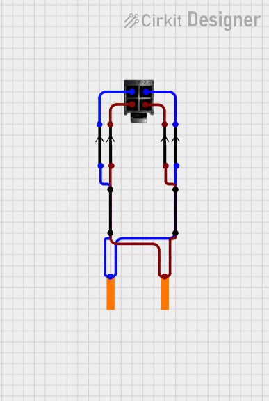 Open Project in Cirkit Designer
 Open Project in Cirkit Designer
Explore Projects Built with 4 pin header
Open Project in Cirkit DesignerOpen Project in Cirkit DesignerOpen Project in Cirkit DesignerOpen Project in Cirkit DesignerCommon Applications and Use Cases
- Connecting sensors, modules, or peripherals to microcontrollers.
- Establishing power and signal connections on PCBs.
- Prototyping circuits on breadboards.
- Creating modular and detachable connections in electronic devices.
Technical Specifications
Key Technical Details
- Number of Pins: 4
- Pin Spacing (Pitch): Typically 2.54 mm (0.1 inch)
- Current Rating: Varies, typically up to 3A per pin (check manufacturer specs)
- Voltage Rating: Typically up to 250V (check manufacturer specs)
- Material: Pins are usually made of brass or phosphor bronze with a tin or gold plating.
- Temperature Range: -40°C to +105°C (varies by manufacturer)
Pin Configuration and Descriptions
The 4 pin header does not have a predefined pinout, as it is a generic connector. However, the pins can be assigned based on the application. Below is an example of a common configuration for a 4 pin header used in a microcontroller project:
| Pin Number | Typical Use Case | Description |
|---|---|---|
| 1 | VCC (Power) | Supplies power to the connected device. |
| 2 | GND (Ground) | Provides a common ground reference. |
| 3 | Signal/Data Line 1 | Transmits or receives data. |
| 4 | Signal/Data Line 2 | Transmits or receives data. |
Note: Always refer to the specific circuit or device documentation to determine the correct pin assignments.
Usage Instructions
How to Use the Component in a Circuit
- Soldering: If using the 4 pin header on a PCB, solder the pins securely into the designated holes. Ensure proper alignment and spacing.
- Breadboard Use: Insert the pins into a breadboard for prototyping. The 2.54 mm pitch is compatible with standard breadboards.
- Connecting Wires: Use female jumper wires or connectors to attach components or modules to the header.
- Pin Assignment: Assign each pin a specific function (e.g., power, ground, signal) based on your circuit design.
Important Considerations and Best Practices
- Check Pinout: Always verify the pinout of the header in your circuit to avoid incorrect connections.
- Avoid Overcurrent: Do not exceed the current rating of the pins to prevent overheating or damage.
- Secure Connections: Ensure that jumper wires or connectors are firmly attached to avoid loose connections.
- Plating Type: For high-reliability applications, consider using gold-plated headers to reduce oxidation and improve conductivity.
Example: Connecting a 4 Pin Header to an Arduino UNO
Below is an example of how to connect a 4 pin header to an Arduino UNO for interfacing with a sensor:
Circuit Setup
- Pin 1 (VCC) connects to the Arduino's 5V pin.
- Pin 2 (GND) connects to the Arduino's GND pin.
- Pin 3 (Signal 1) connects to Arduino digital pin 2.
- Pin 4 (Signal 2) connects to Arduino digital pin 3.
Arduino Code Example
// Example code for reading data from a sensor connected via a 4 pin header

const int signalPin1 = 2; // Pin 3 of the header connected to digital pin 2
const int signalPin2 = 3; // Pin 4 of the header connected to digital pin 3

void setup() {
  pinMode(signalPin1, INPUT); // Set signalPin1 as input
  pinMode(signalPin2, INPUT); // Set signalPin2 as input
  Serial.begin(9600);         // Initialize serial communication
}

void loop() {
  int value1 = digitalRead(signalPin1); // Read data from signalPin1
  int value2 = digitalRead(signalPin2); // Read data from signalPin2

  // Print the values to the Serial Monitor
  Serial.print("Signal 1: ");
  Serial.println(value1);
  Serial.print("Signal 2: ");
  Serial.println(value2);

  delay(500); // Wait for 500ms before reading again
}
Note: Modify the code as needed based on the specific sensor or module being used.
Troubleshooting and FAQs
Common Issues Users Might Face
Loose Connections: Wires or connectors may not be securely attached to the header.
- Solution: Ensure all connections are tight and properly aligned.
Incorrect Pinout: Misidentifying the pin functions can lead to circuit malfunction.
- Solution: Double-check the pinout in your circuit design or device documentation.
Overcurrent or Overvoltage: Exceeding the rated current or voltage can damage the header or connected components.
- Solution: Verify the current and voltage requirements of your circuit before connecting.
Oxidation of Pins: Over time, the pins may oxidize, leading to poor conductivity.
- Solution: Use gold-plated headers for long-term reliability or clean the pins with isopropyl alcohol.
FAQs
Q: Can I use a 4 pin header for both power and data connections?
A: Yes, a 4 pin header can be used for both power and data connections. Just ensure that the pin assignments are clearly defined and do not exceed the current or voltage ratings.
Q: Are 4 pin headers compatible with breadboards?
A: Yes, most 4 pin headers with a 2.54 mm pitch are compatible with standard breadboards.
Q: How do I prevent accidental disconnections?
A: Use locking connectors or secure the wires with heat shrink tubing to prevent accidental disconnections.
Q: Can I cut a longer header strip to make a 4 pin header?
A: Yes, you can cut a longer header strip to the desired length using wire cutters. Be careful to avoid damaging the pins.
By following this documentation, you can effectively use a 4 pin header in your electronic projects!