How to Use VEML6075: Examples, Pinouts, and Specs
Introduction
The VEML6075 is a sophisticated sensor that measures UVA and UVB light intensity, allowing for the calculation of the UV index, an important measure of the strength of ultraviolet radiation from the sun. This sensor is ideal for wearable devices, weather stations, or any application where monitoring UV exposure is necessary.
Explore Projects Built with VEML6075

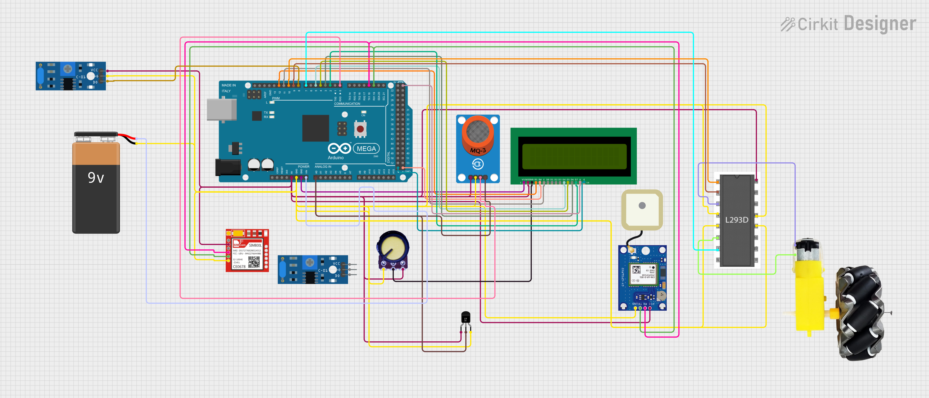

Explore Projects Built with VEML6075
Common Applications and Use Cases
- Personal UV exposure monitoring devices
- Weather stations
- Smartwatches and fitness trackers
- Environmental monitoring systems
Technical Specifications
Key Technical Details
- Operating Voltage: 1.7V to 3.6V
- Interface: I²C protocol
- I²C Address: 0x10 (default)
- Spectral Range: UVA: 365 nm, UVB: 330 nm
- UV Sensitivity: UVA: 365-315 nm, UVB: 280-320 nm
- Resolution: 16-bit per channel (UVA and UVB)
- Operating Temperature: -40°C to +85°C
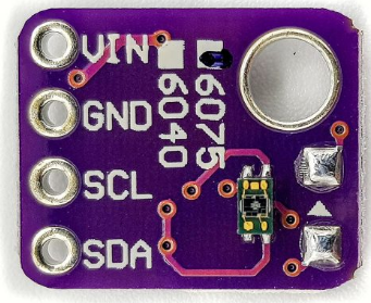
Pin Configuration and Descriptions
| Pin Number | Name | Description |
|---|---|---|
| 1 | VDD | Power supply (1.7V to 3.6V) |
| 2 | GND | Ground connection |
| 3 | SDA | I²C Data line |
| 4 | SCL | I²C Clock line |
| 5 | NC | No connection (leave unconnected) |
Usage Instructions
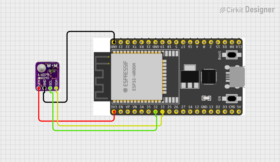
How to Use the VEML6075 in a Circuit
- Power Supply: Connect the VDD pin to a power supply between 1.7V and 3.6V and the GND pin to the ground.
- I²C Communication: Connect the SDA and SCL pins to the corresponding I²C data and clock lines on your microcontroller.
- Initialization: Initialize the sensor using the I²C interface to start measurements.
- Data Reading: Read the UVA and UVB data registers to obtain the light intensity measurements.
Important Considerations and Best Practices
- Ensure that the power supply is within the specified voltage range to prevent damage.
- Use pull-up resistors on the I²C lines if they are not provided by the microcontroller.
- Avoid exposing the sensor to direct sunlight for extended periods to prevent sensor degradation.
- Calibrate the sensor if accurate UV index measurements are required.
Example Code for Arduino UNO
#include <Wire.h>

// VEML6075 I2C address
#define VEML6075_ADDR 0x10

// Register addresses
#define UV_CONF_REG 0x00 // Configuration register
#define UVA_DATA_REG 0x07 // UVA data register
#define UVB_DATA_REG 0x09 // UVB data register

void setup() {
  Wire.begin(); // Initialize I2C
  Serial.begin(9600); // Start serial communication

  // Configure VEML6075
  Wire.beginTransmission(VEML6075_ADDR);
  Wire.write(UV_CONF_REG);
  Wire.write(0x00); // Configuration settings (if any)
  Wire.endTransmission();
}

void loop() {
  // Read UVA and UVB data
  uint16_t uva = readUVData(UVA_DATA_REG);
  uint16_t uvb = readUVData(UVB_DATA_REG);

  // Calculate UV index (simplified calculation, calibration may be needed)
  float uvIndex = (uva + uvb) / 2.0;

  // Print UV index
  Serial.print("UV Index: ");
  Serial.println(uvIndex);

  delay(1000); // Wait for 1 second before the next reading
}

uint16_t readUVData(byte reg) {
  Wire.beginTransmission(VEML6075_ADDR);
  Wire.write(reg);
  Wire.endTransmission();

  Wire.requestFrom(VEML6075_ADDR, 2);
  if (Wire.available() == 2) {
    // Read two bytes from the sensor
    uint16_t data = Wire.read();
    data |= Wire.read() << 8;
    return data;
  } else {
    return 0; // Error in communication
  }
}
Troubleshooting and FAQs
Common Issues Users Might Face
- No Data: Ensure that the sensor is properly powered and that the I²C lines are correctly connected.
- Inaccurate Readings: Calibration may be necessary for precise UV index measurements.
Solutions and Tips for Troubleshooting
- Check Connections: Verify that all connections are secure and correct.
- I²C Address Conflict: Ensure that no other device on the I²C bus has the same address.
- Sensor Calibration: Follow the manufacturer's guidelines for calibrating the sensor for accurate readings.
FAQs
Q: Can the VEML6075 sensor be used with a 5V microcontroller? A: Yes, but a level shifter is recommended for the I²C lines, and the VDD must be within the 1.7V to 3.6V range.
Q: How often should the sensor be calibrated? A: Calibration frequency depends on the application's accuracy requirements and the sensor's exposure to harsh conditions.
Q: Is the VEML6075 sensor waterproof? A: No, the VEML6075 is not inherently waterproof. Additional protection is required for outdoor applications.